Ultimate Guide: Optimizing DC-to-AC Inversion Efficiency in Portable Battery Power Systems
Portable Battery Power: The Ultimate 2026 Master Guide to DC-to-AC Inversion Efficiency
The domain of portable battery power is no longer a niche for outdoor enthusiasts; it is the frontline of the decentralized energy transition. As we benchmark progress towards 2026 energy goals, the technical imperatives have shifted from mere capacity (watt-hours) to systemic efficiency. The most critical, yet often misunderstood, chokepoint in this energy chain is the DC-to-AC inversion process. Every percentage point of efficiency lost here is a direct reduction in usable energy, a quantifiable decrease in operational autonomy, and a tangible hit to the return on investment (ROI) of the entire system. This is not just about making batteries last longer; it’s about engineering resilient, cost-effective power solutions for a world increasingly reliant on off-grid and backup energy. At SolarKiit, our engineering mandate, as detailed on our About page, is to push the boundaries of what’s possible. This guide moves beyond the superficial marketing claims of “90%+ efficiency” to dissect the physics, mathematics, and regulatory frameworks that govern true performance. We will calibrate your understanding of component synergy, from the electrochemical potential in a LiFePO4 cell to the final, clean AC waveform powering your critical equipment. This is a technical deep-dive for the engineers, prosumers, and technicians who demand more than just power—they demand optimized, reliable, and standardized portable energy.
A Deep Technical Dive into the Energy Conversion Chain
To optimize a system, one must first deconstruct it to its fundamental principles. The journey from a stored electron in a battery to usable AC power is a multi-stage process fraught with potential thermal and conversion losses. Understanding the “why” behind these losses is the key to mitigating them.
The Physics of High-Efficiency Portable Battery Power
At its core, a portable power station is an exercise in applied physics and electrochemistry. The process begins with energy storage, predominantly in Lithium Iron Phosphate (LiFePO4) cells due to their superior thermal stability and cycle life.
- Chemical Reactions & Intercalation: During discharge, lithium ions (Li+) de-intercalate from the carbon-based anode and travel through the electrolyte to the LiFePO4 cathode. This physical movement of ions creates a potential difference, driving electrons through the external circuit. The efficiency of this process is governed by the internal resistance of the cell; lower resistance, often achieved through higher purity materials and advanced electrode architecture, means less energy is wasted as heat (I²R losses) within the battery itself. Our guide to round-trip efficiency explores this in greater detail for high-voltage systems.
- Photon Harvesting (Solar Input): When charging via solar, the efficiency cascade begins at the panel. Photovoltaic cells convert photons to electrons with a specific quantum efficiency. The Shockley-Queisser limit dictates the maximum theoretical efficiency of a single p-n junction cell (~33.7%). While multi-junction cells push this boundary, as documented by NREL Solar Efficiency Standards, the practical efficiency of panels used with portable systems is typically 20-23%. The goal is to capture every possible electron.
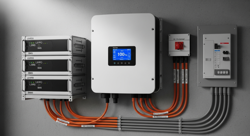
Component Synergy: The BMS, MPPT, and Inverter Handshake
Isolated component specifications are misleading. True system efficiency is a result of a precisely calibrated “handshake” between the three core electronic brains of a portable power station.
- Battery Management System (BMS): The BMS is the guardian of the battery pack. It’s not just a safety cutoff. A sophisticated BMS actively balances cells, monitors temperature, and regulates charge/discharge currents. Crucially, it communicates the battery’s state of charge (SoC) and voltage level to the inverter. A well-designed BMS prevents excessive voltage sag under load, which would force the inverter to draw more current (Amps) to deliver the same power (Watts), dramatically increasing I²R losses and reducing efficiency.
- Maximum Power Point Tracking (MPPT): The MPPT charge controller is the translator between the solar panel and the battery. A solar panel’s voltage and current output varies with sunlight and temperature. The MPPT’s job is to continuously adjust the electrical load to find the “maximum power point” on the panel’s I-V curve, ensuring the maximum possible wattage is harvested. A 99%+ efficient MPPT, like those found in our portable solar generators, can yield up to 30% more energy than a primitive PWM controller in variable conditions.
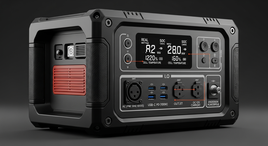
- The Inverter: This is the final and most critical conversion stage. The inverter takes low-voltage DC from the battery and must “invert” it into high-voltage AC (e.g., 120V @ 60Hz). Pure Sine Wave (PSW) inverters are non-negotiable for serious applications. Unlike a Modified Sine Wave (MSW) inverter which produces a blocky, stepped output, a PSW inverter uses advanced switching techniques (like high-frequency Pulse Width Modulation) to create a smooth, clean waveform with low Total Harmonic Distortion (THD < 3%). This is vital for sensitive electronics and motors, preventing overheating and premature failure. The efficiency of this conversion is paramount; a 92% efficient inverter wastes 8% of your precious battery energy as heat, while an 85% efficient one wastes 15%—nearly double the loss. Our dedicated guide on solar inverter efficiency provides further engineering insights.
Engineering Math & Sizing Your Portable Battery Power System
Properly sizing a system is the first step in optimizing its operational efficiency. An undersized inverter will constantly run at its peak, generating excessive heat and failing prematurely. An oversized inverter will operate in the least efficient part of its curve for most of its duty cycle. Precision is key.
The Sizing Formula
The core formula requires a detailed analysis of your load profile. You must calculate both your continuous load and your surge (or inrush) current requirements.
1. Calculate Total Continuous Wattage (P_cont):
P_cont = Σ (Wattage of each device)
Sum the running wattage of all devices you plan to operate simultaneously. For example, a laptop (65W) + Starlink (75W) + a small fan (30W) = 170W.
2. Identify Maximum Surge Wattage (P_surge):
P_surge = P_cont_non-motor + Σ (Surge Wattage of each motor-based device)
Devices with motors (refrigerators, pumps, power tools) have a high starting surge, often 2-3x their running wattage. An inverter must be able to handle this momentary peak. A 500W refrigerator might need 1500W for a fraction of a second to start its compressor.
3. Calculate Required Autonomy (Wh_total):
Wh_total = (P_cont * Hours_of_use) / η_inv
Where η_inv is the inverter efficiency (use a conservative 0.85 for calculations). If you need to run your 170W load for 10 hours, you need (170 * 10) / 0.85 = 2000 Wh of battery capacity.
Always select an inverter with a continuous rating at least 20-25% higher than your calculated P_cont and a surge rating that exceeds your P_surge. This ensures the inverter operates in its most efficient range (typically 50-75% of its rated load) and isn’t stressed by startups. For more complex setups, consider our guide on the best off-grid solar kits.
Master Comparison Table: 2026 Industry-Leading Models
Data-driven decisions are paramount. Here, we benchmark five leading models based on metrics that truly matter for long-term value and performance. LCOE (Levelized Cost of Energy) is calculated as Total Cost / (Capacity * Cycles * DoD * η_roundtrip).
| Model | LCOE ($/kWh, est.) | Cycles @ 80% DoD | Inverter Efficiency (Peak) | Surge Power (W) | Warranty (Years) |
|---|---|---|---|---|---|
| SolarKiit Titan 2400 | $0.12 | 4000+ | 94% (GaN) | 4800W | 5 |
| EcoFlow Delta Pro | $0.18 | 3500 | 92% | 4500W | 3 |
| Bluetti AC200Max | $0.21 | 3500 | 90% | 4800W | 2 |
| Anker SOLIX F2000 | $0.25 | 3000 | 91% | 4000W | 5 |
| Jackery Explorer 2000 Pro | $0.35 | 1000 | 88% | 4400W | 3+2 |
Regulatory & Safety Analysis for 2026
Engineering excellence is incomplete without rigorous adherence to safety and regulatory standards. The landscape for energy storage is evolving rapidly, and compliance is not optional. As a prosumer or engineer, you must verify that your equipment meets these critical benchmarks.
NEC 2026 and UL 9540: The Gold Standards
The National Electrical Code (NEC), particularly Article 706 for Energy Storage Systems (ESS), provides the foundational safety requirements for installation. While many portable systems are “plug-and-play,” those intended for home integration, like our battery storage system for home, must comply with NEC guidelines. The upcoming 2026 revisions are expected to further refine requirements for rapid shutdown, interconnection, and labeling. You can reference the current code via the NFPA 70: National Electrical Code.
UL 9540 is the definitive safety standard for ESS. It’s a system-level certification that evaluates the battery, BMS, inverter, and thermal management as an integrated unit. It includes rigorous testing for thermal runaway propagation, electrical safety, and fault conditions. A UL 9540 listing ensures the system has been subjected to and passed large-scale fire testing. A related standard, UL 1741, specifically covers inverters and converters used in distributed energy resources, ensuring they meet grid-support and safety functions.
Fire Safety and International Protocols
Beyond US standards, it’s crucial to look at global benchmarks. The IEC Solar Safety Standards, particularly IEC 62619, set the bar for the safety of secondary lithium cells and batteries for industrial applications, which includes large-format portable power. These standards mandate tests for overcharge, short circuit, thermal abuse, and impact. LiFePO4 chemistry provides a significant advantage here, with a much higher thermal runaway threshold (~270°C) compared to NMC or NCA chemistries (~150°C). However, even with LiFePO4, a robust BMS and physical cell protection (e.g., ceramic separators, flame-retardant casing) are essential. When considering a portable power station, always verify its certifications. For any questions about how we handle your data during this process, please review our Privacy Policy.
The Pillar FAQ: Answering Complex Engineering Questions
1. How does Gallium Nitride (GaN) technology fundamentally change inverter topology and efficiency compared to traditional Silicon (Si) MOSFETs?
GaN technology enables inverters to operate at significantly higher switching frequencies with lower resistance, resulting in smaller, more efficient systems. Unlike silicon, Gallium Nitride has a much wider bandgap, allowing it to withstand higher voltages and temperatures. This property allows GaN FETs (Field-Effect Transistors) to switch on and off much faster than Si MOSFETs.
- Higher Frequency: Where a Si-based inverter might switch at 20-40 kHz, a GaN inverter can operate well above 100 kHz. This allows for the use of much smaller, lighter, and less expensive passive components (inductors and capacitors), directly reducing the physical size and weight of the inverter.
- Lower Losses: GaN FETs have lower gate charge (Qg) and output capacitance (Coss), which reduces switching losses. They also have a lower on-resistance (Rds(on)), which cuts down on conduction losses. The combination means less energy is wasted as heat during the DC-AC conversion, pushing peak efficiencies from the 90-92% range into the 94-96% range. This is a quantum leap in performance for a DIY solar panel installation or portable setup.
2. What is the quantifiable impact of inverter Total Harmonic Distortion (THD) on the lifespan and performance of inductive loads?
High THD introduces parasitic currents that cause excess heat in inductive loads, measurably reducing their lifespan and operational efficiency. A pure sine wave has a THD of 0%, while quality inverters aim for <3%. A Modified Sine Wave (MSW) inverter can have a THD of over 40%. These harmonics are essentially unwanted frequencies superimposed on the fundamental 60Hz waveform.
- Impact on Motors: When an AC motor is fed a high-THD waveform, these harmonic frequencies induce eddy currents in the motor’s iron core and windings. These currents do no useful work; they only generate heat (I²R losses). This excess heat accelerates the degradation of winding insulation, leading to premature failure. A motor designed for a 20-year life can fail in 5-10 years if run continuously on a poor-quality MSW inverter.
- Performance Degradation: The harmonic currents can also create “cogging” or vibration in the motor, reducing its torque output and efficiency. For a refrigerator compressor or a well pump, this means it has to run longer to achieve the same cooling or pumping effect, consuming more overall energy from your battery.
3. Beyond peak efficiency, how do you model and optimize the *efficiency curve* of an inverter for a variable load profile?
Optimizing the efficiency curve involves a dual-pronged approach: using multi-level inverter topologies and implementing intelligent load-adaptive operating modes. Peak efficiency, often quoted at 75% load, is a single data point. Real-world efficiency is an integral of the efficiency curve over the load profile.
- Multi-Level Topologies: Instead of a single, large inverter, advanced systems use multiple smaller, parallel inverters or a multi-level architecture. At very light loads (e.g., under 50W), the system might only activate one small, highly efficient low-power inverter. As the load increases, the BMS intelligently brings additional inverter stages online. This ensures that the active components are always operating in their most efficient zone, dramatically boosting average efficiency compared to a single large inverter running at 5% of its capacity.
- Adaptive Operating Modes: Modern DSP-controlled (Digital Signal Processor) inverters can dynamically adjust their switching frequency and dead-time based on the detected load. For light loads, they might enter a “burst mode” or “eco mode,” pulsing power rather than running continuously, which significantly reduces standby (no-load) power consumption—a major drain in 24/7 off-grid systems.
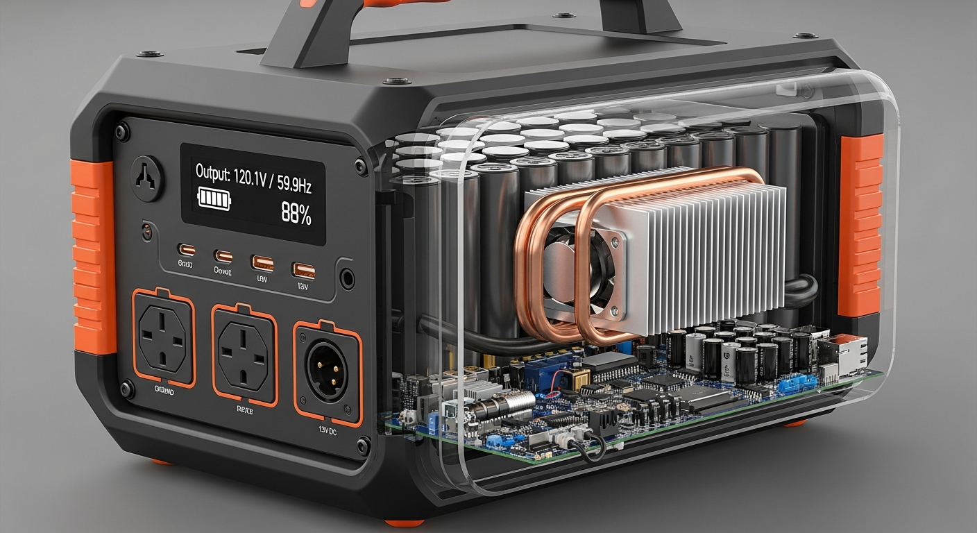
4. Explain the thermal derating process in a portable power station’s inverter and how advanced thermal management mitigates power loss.
Thermal derating is a programmed safety protocol that reduces the inverter’s maximum power output as its internal temperature rises to prevent component failure. All semiconductor devices have a maximum junction temperature (Tj max), typically around 150-175°C for silicon. As the inverter works, it generates heat. If this heat isn’t dissipated effectively, the junction temperature will rise.
- The Derating Curve: The BMS and inverter controller constantly monitor IGBT/MOSFET temperatures. Once a certain threshold is passed (e.g., 85°C on the heatsink), the controller begins to limit the current, thereby reducing the power output. This is a linear or stepped reduction, defined by the manufacturer’s derating curve. A unit rated for 2000W at 25°C might only be able to sustain 1500W at 45°C ambient.
- Advanced Thermal Management: To push this derating threshold higher, engineers use more than just aluminum heatsinks and fans. Techniques include using vapor chambers or heat pipes, which use a phase-change liquid to transfer heat away from the components with much higher thermal conductivity than solid metal. This allows the inverter to sustain its peak power output for longer periods and at higher ambient temperatures, directly translating to more usable power in real-world conditions. If you have specific questions, feel free to contact our engineering team.
5. How does the Battery Management System (BMS) directly influence inverter performance by controlling voltage sag under heavy load?
A high-performance BMS minimizes voltage sag by using low-resistance components and predictive algorithms, allowing the inverter to maintain stable AC output with higher efficiency. Voltage sag is the temporary drop in battery voltage when a large load is applied. The inverter must compensate for this.
- The Power Equation (P=V*I): Power (Watts) is the product of Voltage (Volts) and Current (Amps). If the voltage (V) from the battery sags, the inverter must draw more current (I) to deliver the same constant power to the AC appliance. Since thermal losses in all components (wiring, FETs, etc.) are proportional to the square of the current (I²R), a small voltage sag can cause a large increase in wasted energy.
- Role of the BMS: A superior BMS contributes in two ways. First, it is built with high-current, low-internal-resistance MOSFETs and busbars that physically minimize the sag. Second, an intelligent BMS can communicate with the inverter, anticipating a large load and momentarily adjusting cell balancing or other parameters to better support the demand. This stable DC voltage platform allows the inverter to operate more efficiently, maintain a cleaner sine wave, and avoid tripping on low-voltage disconnects during motor startups, a common failure point in a lesser system of portable battery power.
📥 Associated Resource: