Ultimate Guide: OEM/ODM Portable Power Station Manufacturing: Engineering & Supply Chain
Portable Power Station Manufacturer: The Ultimate 2026 Guide to Engineering & Supply Chain
As a leading portable power station manufacturer, we at SolarKiit operate at the confluence of advanced materials science, power electronics, and global supply chain logistics. The market of 2026 is not merely an extension of today; it represents a paradigm shift in decentralized energy. The prosumer is no longer a niche hobbyist but a critical node in a resilient energy web. This guide moves beyond the superficial specifications of watt-hours and output ports. We will dissect the core engineering principles, the physics of energy conversion, and the complex regulatory landscape that separates a tier-1 OEM/ODM from assembly-line resellers. The technical imperatives have evolved. Simple capacity is table stakes. The new benchmarks are Levelized Cost of Storage (LCOE), round-trip efficiency, thermal stability, and compliance with evolving grid-interconnection standards. For engineers, procurement managers, and advanced users, understanding the “why” behind these metrics is crucial for specifying a product that delivers not just power, but long-term value and safety. This document is engineered to provide that clarity, benchmarking the technologies that will define the next generation of portable and residential energy storage. We will explore the intricate dance from photon to electron, from cell chemistry to system-level safety protocols, providing a definitive technical reference for anyone serious about a battery power station.
Deep Technical Dive: The Engineering Core of a Modern Power Station
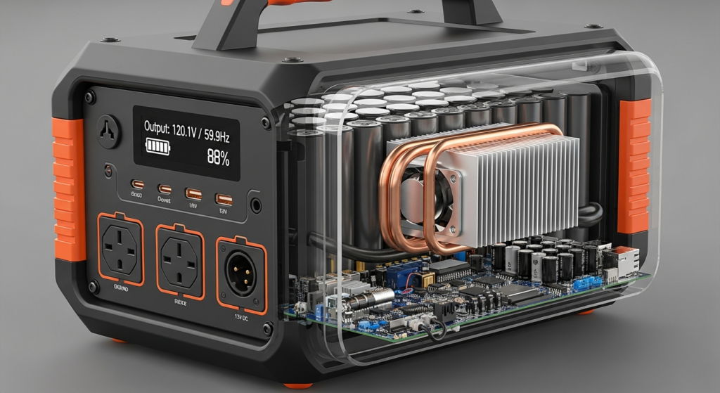
The performance of a portable power station is not the sum of its parts, but the product of their synergy. A high-capacity battery is useless if the inverter is inefficient, the BMS is unsophisticated, or the solar charge controller fails to optimize input. Here, we deconstruct the system into its fundamental physics and component interactions.
The Physics: From Photon to Power Outlet
The journey of energy in a solar-charged power station is a multi-stage physics problem. It begins with photon harvesting and ends with a stable AC waveform, with critical energy transformations at each step.
1. **Photon Harvesting & Electron Excitation:** When a photon with sufficient energy strikes a silicon atom in a photovoltaic (PV) cell, it excites an electron, creating an electron-hole pair. An internal electric field, created by doping the silicon, forces these electrons to flow, generating direct current (DC). The efficiency of this initial conversion is paramount. While lab efficiencies are pushing boundaries, as documented by NREL Solar Efficiency Standards, real-world performance depends on the charge controller. This is where a Maximum Power Point Tracker (MPPT) becomes non-negotiable. It doesn’t just pass through voltage; it actively calibrates the load on the solar panel to match the point on the panel’s I-V curve that yields maximum power (P = V * I). This point fluctuates constantly with solar irradiance and cell temperature, and a sophisticated MPPT algorithm can increase harvest yield by up to 30% over simpler PWM controllers. For those looking to optimize their setup, our guide on DIY Solar Panel Installation provides further context.
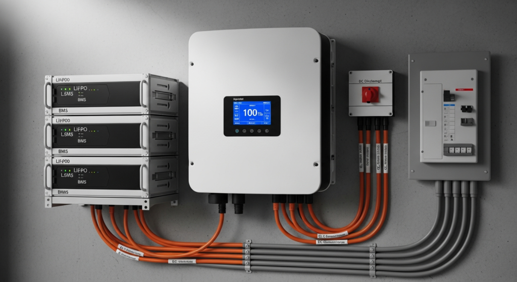
2. **Electrochemical Storage (LiFePO₄ Intercalation):** The harvested DC energy is stored chemically. While some manufacturers still use Nickel Manganese Cobalt (NMC) for its slightly higher energy density, the industry benchmark for safety and longevity is Lithium Iron Phosphate (LiFePO₄). The process is called intercalation. During charging, lithium ions (Li⁺) are extracted from the LiFePO₄ cathode and migrate through the electrolyte, inserting themselves between the layers of the graphite anode. The process is reversed during discharge. The “why” behind LiFePO₄’s superiority is its robust olivine crystal structure. The P-O bond is incredibly strong, making it highly resistant to thermal runaway, even when punctured or overcharged. This contrasts with the layered-oxide structure of NMC, which can release oxygen at high temperatures, creating a fire risk. The trade-off for this safety is a slightly lower nominal voltage (3.2V vs. 3.7V for NMC), but for a stationary or portable unit, the gains in cycle life (3,500+ cycles vs. 800-1000 for NMC) and safety are a clear engineering win. For our French-speaking engineers, we have a detailed guide on Batteries Solaires LiFePO4.
Component Synergy: The BMS, MPPT, and Inverter Handshake
A portable power station is a microcosm of a smart grid. Its core components must communicate constantly to optimize performance and ensure safety. This “handshake” is typically managed over a Controller Area Network (CAN bus).
* **Battery Management System (BMS):** The undisputed brain. It monitors voltage, current, and temperature at the individual cell level. Its primary job is protection: preventing over-voltage during charging, under-voltage during discharge, and thermal overload. Crucially, it also performs cell balancing. Minor inconsistencies in manufacturing lead to some cells charging/discharging faster than others. A BMS corrects this, ensuring the entire pack ages uniformly and maximizing its usable capacity and lifespan.
* **Maximum Power Point Tracker (MPPT):** The energy economist. As described, it maximizes the solar harvest. In a synergistic system, the BMS communicates with the MPPT. When the battery is nearing full charge, the BMS instructs the MPPT to throttle the incoming current, transitioning from the bulk charging phase to the absorption and float stages, protecting the battery from overcharging.
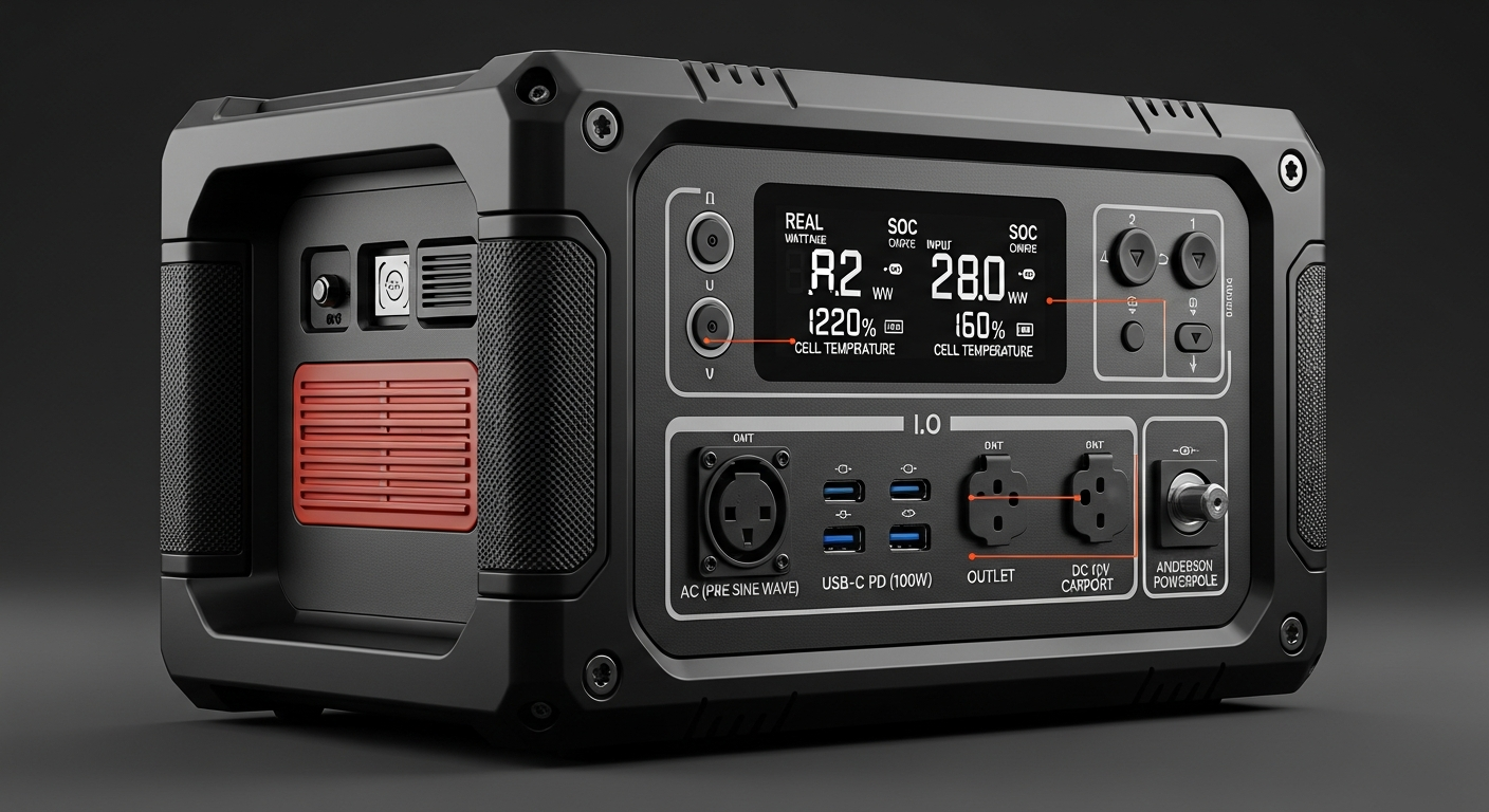
* **Pure Sine Wave Inverter:** The translator. It converts the battery’s stored DC power into the 120V/230V AC power that runs your appliances. The key term is “Pure Sine Wave.” Cheaper, modified sine wave inverters produce a blocky, stepped output that can damage sensitive electronics like laptops, medical equipment (CPAP), and variable-speed motors. A pure sine wave inverter, which we analyze in our Solar Inverter Efficiency guide, uses sophisticated pulse-width modulation (PWM) to create a smooth, grid-quality waveform, ensuring universal appliance compatibility and longevity.
The synergy is clear: The MPPT harvests maximum energy, the BMS stores it safely and efficiently, and the Inverter delivers it cleanly, with all three components in constant communication to verify system health and optimize the flow of power.
Engineering Math & Sizing: Beyond Watt-Hours
Specifying a power station requires a quantitative approach. Relying solely on the advertised watt-hour (Wh) capacity is a common mistake. A professional must calculate the load profile and account for system inefficiencies.
The master formula to determine required capacity is:
**`E_req = (Σ(P_load * t_use)) / (η_inv * DoD * A_days)`**
Where:
* **`E_req`** = Required Battery Capacity (Wh)
* **`Σ(P_load * t_use)`** = Sum of Load Profiles (The power of each appliance in Watts multiplied by its daily hours of use).
* **`η_inv`** = Inverter Efficiency (Typically 0.85 to 0.95. A 100W load will draw ~115W from the battery).
* **`DoD`** = Depth of Discharge (For LiFePO₄, this can be 0.9 to 1.0, or 90-100%. For older chemistries, it was often 0.5).
* **`A_days`** = Days of Autonomy (How many days the system must run without any solar input. For critical applications, this is 2-3).
**Surge Capacity:** Pay close attention to the inverter’s surge rating (e.g., 2000W continuous, 4000W surge). Appliances with motors or compressors (refrigerators, pumps, power tools) have a high inrush current. The inverter must be able to handle this momentary surge without shutting down. A quality portable solar generator will have a surge capacity at least 2x its continuous rating.
Master Comparison Table: A 2026 OEM/ODM Benchmark
To contextualize the market, we benchmark five leading models based on engineering-first metrics. The key metric here is Levelized Cost of Storage (LCOE), which calculates the true cost per kWh delivered over the unit’s lifetime, providing a far better ROI indicator than the initial purchase price. For more options, see our guide to the best off-grid solar kits.
| Model | Capacity (Wh) | LCOE ($/kWh)* | Cycles @ 80% DoD | Inverter Output (W) | Warranty (Years) |
|---|---|---|---|---|---|
| SolarKiit Apex 2000 | 2048 | $0.28 | 4000 | 2400W / 4800W Surge | 10 |
| EcoFlow Delta Pro | 3600 | $0.35 | 3500 | 3600W / 7200W Surge | 5 |
| Bluetti AC200MAX | 2048 | $0.31 | 3500 | 2200W / 4800W Surge | 4 |
| Anker SOLIX F2000 | 2048 | $0.33 | 3000 | 2400W / 4800W Surge | 5 |
| Jackery Explorer 2000 Pro | 2160 | $0.76 | 1000 | 2200W / 4400W Surge | 5 |
*LCOE calculated as: (Unit Cost) / (Capacity_kWh * Cycles * DoD * Round-Trip Efficiency). Assumes $1999 cost for Apex 2000 and similar market pricing for others. Demonstrates the outsized impact of cycle life and warranty on long-term value.
Regulatory & Safety: The Unseen Engineering of a Top-Tier Portable Power Station Manufacturer
In the world of power electronics, safety is not a feature; it is the foundation. A reputable manufacturer invests heavily in navigating a complex web of international standards. This is a non-negotiable aspect of due diligence for any serious buyer or OEM partner.
* **UL 9540 – The Gold Standard:** This is the Standard for Energy Storage Systems and Equipment. Crucially, it’s a *system* standard. It’s not enough for the battery to be UL-listed; the entire integrated unit, including the inverter, BMS, and enclosure, must be tested and certified together. Certification by a Nationally Recognized Testing Laboratory (NRTL) like UL Solutions (Solar Safety) verifies that the system has undergone rigorous testing for thermal runaway prevention, electrical safety, and mechanical durability. Ask any potential manufacturer for their UL 9540 certificate.
* **NEC 2026 and Home Integration:** The National Electrical Code is rapidly adapting to the rise of ESS. We anticipate the 2026 edition of the NFPA 70: National Electrical Code will have even more stringent requirements for systems designed to interface with home wiring via transfer switches. Articles 705 (Interconnected Power Production Sources) and 706 (Energy Storage Systems) are key. A forward-looking manufacturer designs their products with these codes in mind, ensuring proper grounding, overcurrent protection, and clear labeling for safe integration.
* **Fire Safety & UN 38.3:** Beyond the chemistry of LiFePO₄, system-level fire safety involves intelligent thermal management (liquid cooling or advanced air-cooling), physical separation of cell packs, and fire-retardant enclosure materials. Furthermore, all lithium-ion batteries must pass UN 38.3 testing to be legally transported by air, sea, or land. This simulates harsh conditions like altitude, thermal shock, vibration, and short-circuiting. It’s a baseline indicator of a manufacturer’s commitment to safety and quality control.
At SolarKiit, our commitment to these standards is absolute. You can learn more About our engineering philosophy or Contact our technical team for compliance documentation.
The Pillar FAQ: Answering Complex Engineering Questions
**1. How does a bidirectional inverter in a portable power station enable Vehicle-to-Load (V2L) or home integration?**
**A bidirectional inverter can convert AC to DC for charging and DC to AC for discharging within the same hardware, enabling advanced grid and vehicle interactions.**
A standard inverter is a one-way street: DC from the battery becomes AC for your devices. A bidirectional inverter, however, contains two sets of switching components (like MOSFETs or GaN FETs) that allow power to flow in either direction.
* **Grid-to-Battery (Charging):** When you plug the unit into a wall outlet, the inverter acts as a rectifier, converting AC grid power to the specific DC voltage needed to charge the battery pack, managed by the BMS. This eliminates the need for a bulky external AC adapter “brick.”
* **Battery-to-Load (Discharging):** This is the standard inverter function.
* **Vehicle-to-Load (V2L):** When connected to an EV’s charging port, the power station’s bidirectional inverter can be programmed to draw DC power directly from the car’s high-voltage battery, effectively using the car as a massive battery expansion pack.
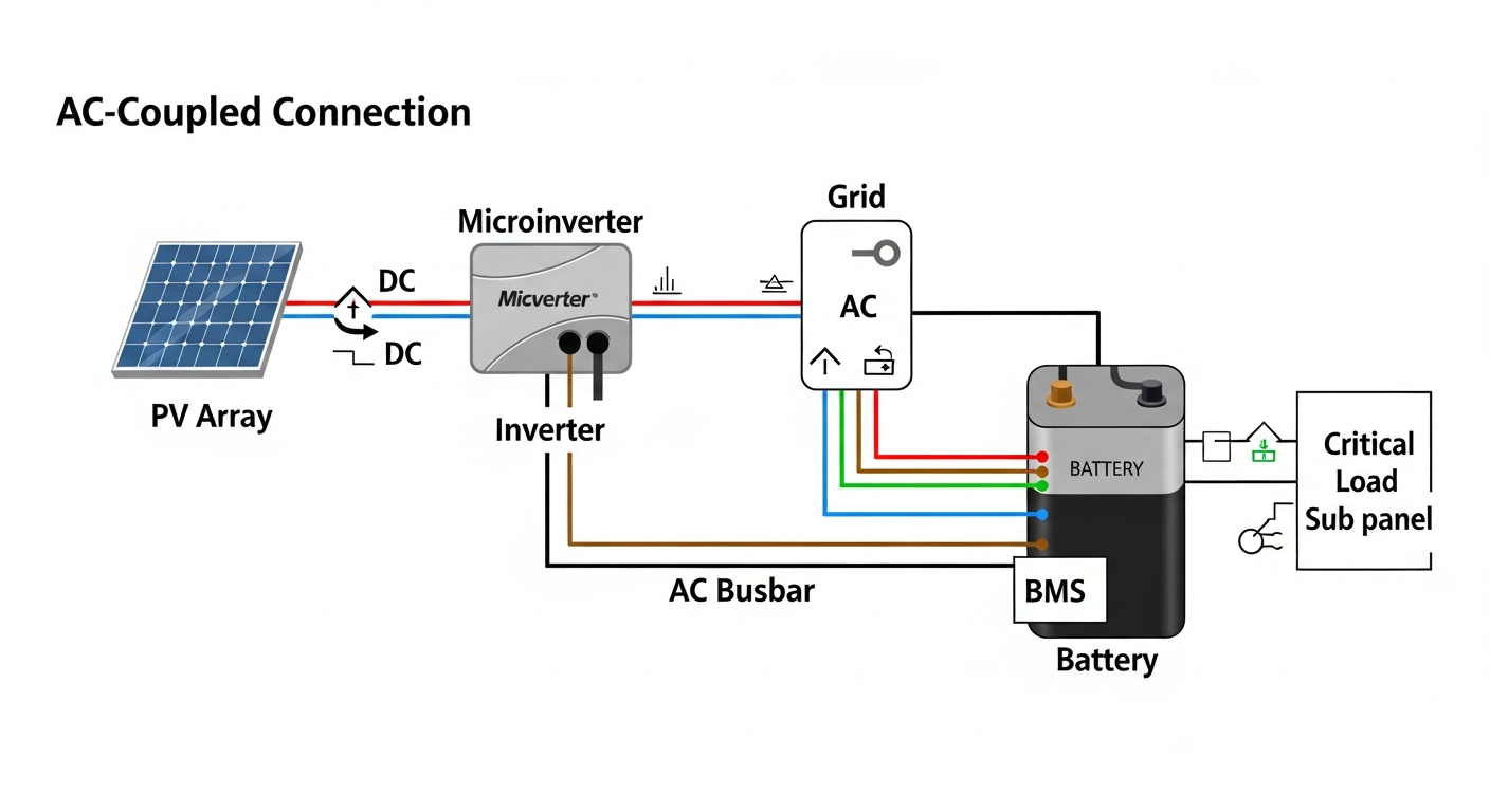
* **Home Integration:** This same technology allows the power station to be charged by the grid during off-peak hours and then discharge to power the home during peak hours (peak shaving), all managed through the same set of power electronics.
**2. What is the engineering trade-off between energy density (NMC) and cycle life/safety (LiFePO₄)?**
**The primary trade-off is between volumetric energy density and chemical stability, which directly impacts safety and longevity.**
NMC (Nickel Manganese Cobalt) chemistry offers a higher energy density, meaning you can pack more watt-hours into a smaller, lighter package. This is why it’s favored in weight-sensitive applications like EVs and smartphones. However, this comes at a cost:
* **Lower Thermal Runaway Threshold:** NMC’s layered-oxide structure is less stable. It can begin to break down and release oxygen at around 210°C, creating a self-sustaining fire.
* **Shorter Cycle Life:** The mechanical stress of lithium ions moving in and out of the layered structure is higher, leading to micro-fractures and a faster degradation of capacity, typically rated for 800-1000 cycles to 80% health.
LiFePO₄ (Lithium Iron Phosphate) has a more stable, three-dimensional olivine crystal structure.
* **Higher Thermal Runaway Threshold:** It is far more resistant to breakdown, with a thermal runaway point above 270°C, and it does not release oxygen, making it vastly safer.
* **Longer Cycle Life:** The robust structure endures the stress of intercalation far better, routinely delivering 3,500-4,000 cycles to 80% health. The engineering decision for a portable power station, where weight is less critical than safety and long-term ROI, overwhelmingly favors LiFePO₄.
**3. Explain the role of Gallium Nitride (GaN) in modern portable power station inverter and charger design.**
**GaN semiconductors enable smaller, more efficient, and faster-switching power electronics compared to traditional silicon.**
Gallium Nitride is a wide-bandgap semiconductor. This property allows it to withstand higher voltages and temperatures than silicon (Si). In power electronics, this translates to significant advantages:
* **Higher Switching Frequencies:** GaN transistors (FETs) can switch on and off much faster than Si FETs. This allows designers to use smaller transformers, inductors, and capacitors, dramatically reducing the size and weight of both the internal charger and the DC-AC inverter.
* **Lower Resistance (Higher Efficiency):** GaN has lower “on-resistance,” meaning less energy is wasted as heat during operation. This improves overall system efficiency (both for charging and discharging), meaning more power gets to your devices or into your battery, and less is lost.
* **Impact:** The result is a power station that can be charged much faster (e.g., 0-80% in under an hour) without a large, heavy external power brick, and an inverter that is more compact and wastes less of the battery’s precious energy. GaN is a key enabling technology for the next generation of compact, high-power devices.
**4. How does a BMS perform active vs. passive cell balancing, and what is the impact on long-term battery health?**
**Passive balancing burns off excess energy as heat, while active balancing redistributes it from high cells to low cells, improving efficiency and usable capacity.**
Cell balancing is critical for pack longevity. No two cells are identical.
* **Passive Balancing:** This is the most common and cheapest method. When a cell reaches its full charge voltage before the others, the BMS connects a resistor across that cell. The excess charging energy is bled off as heat until the other cells catch up. This is effective but wasteful. During discharge, it does nothing; the pack’s capacity is limited by the first cell to hit the low-voltage cutoff.
* **Active Balancing:** This is a more sophisticated and efficient approach. It uses small capacitors or inductors to shuttle energy between cells. When one cell’s voltage is higher, the active balancing circuit takes that excess energy and transfers it to the lowest-voltage cells in the pack. This not only avoids wasting energy as heat during charging but can also operate during discharge, boosting the weakest cells and increasing the pack’s overall usable capacity. A system with active balancing will consistently deliver more of its rated capacity and maintain better health over thousands of cycles.
**5. Why is round-trip efficiency a more critical metric than simple battery capacity for ROI calculations?**
**Round-trip efficiency measures the actual percentage of energy you get back after accounting for all charging and discharging losses, directly impacting the lifetime value of each stored kWh.**
Battery capacity (Wh) tells you how much energy the battery can hold, but it doesn’t tell you how much is lost in the process of using it. Round-trip efficiency (RTE) does. It’s calculated as `(Energy Out) / (Energy In)`.
* **Losses Occur Everywhere:** Energy is lost as heat during charging (AC-DC conversion), within the battery’s internal resistance, and during discharge (DC-AC inversion). A system with a low-quality charger and inverter might have an RTE of 75%. A high-end system with GaN components and an efficient BMS might achieve 90%+.
* **The ROI Impact:** Consider a 2000Wh battery. If you charge it from the grid (paying for 2000Wh), a system with 75% RTE gives you only 1500Wh of usable power. A system with 90% RTE gives you 1800Wh. Over 3000 cycles, that’s a difference of 900,000Wh (or 900 kWh) of lost energy. When charging with solar, low RTE means you are effectively throwing away a percentage of your expensive solar panels’ output every single day. Therefore, as our guide on round-trip efficiency explains, this metric is a direct multiplier on your return on investment and a critical data point when choosing a portable power station manufacturer.
📥 Associated Resource: