Panneau Solaire | Guide Technique d’Ingénierie & Installation 2026
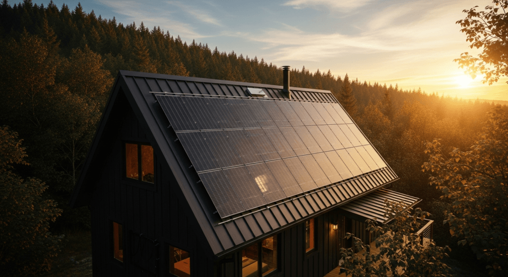
A solar power station in 2026 represents the pinnacle of decentralized energy autonomy, evolving far beyond simple rooftop panels. These integrated systems are now sophisticated energy hubs, combining high-efficiency photovoltaic generation, advanced battery storage, and intelligent power management. As the global energy landscape shifts towards resilience and sustainability, the modern solar power station serves as a critical asset for homeowners and businesses, offering insulation from grid instability and volatile utility pricing.
The market is driven by key technological convergences. Breakthroughs in battery chemistry, particularly Lithium Iron Phosphate (LiFePO4), have made energy storage safer, longer-lasting, and more affordable. Simultaneously, inverter technology has matured, enabling seamless grid integration, off-grid independence, and even participation in Vehicle-to-Grid (V2G) ecosystems. This guide provides an engineering-level deep dive into the components, specifications, and installation protocols defining the state-of-the-art solar power station of 2026.
At SolarKiit, we analyze these systems not as individual components, but as a cohesive whole. From the quantum physics of the PV cell to the National Electrical Code (NEC) compliance of the final installation, every detail matters. This technical brief is engineered for those who demand a granular understanding of how to design, specify, and deploy a robust and future-proofed solar energy solution.
Deep Technical Analysis of a Modern Solar Power Station
Understanding a solar power station requires a multi-layered analysis, beginning with the fundamental physics of energy conversion and extending to the meticulous process of system sizing. By 2026, component efficiencies have reached new benchmarks, demanding a more precise approach to design and engineering.
The Physics of Photovoltaic Energy Conversion
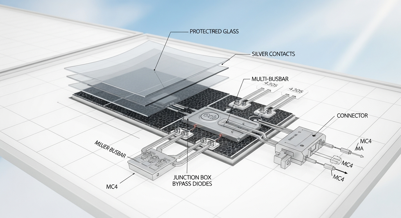
The core of any solar installation is the photovoltaic (PV) cell, a semiconductor device that converts photons into electrons. This process, the photovoltaic effect, occurs within a p-n junction, typically made from silicon. When a photon with sufficient energy strikes the cell, it excites an electron, creating an electron-hole pair. An internal electric field within the junction separates these pairs, forcing electrons to flow into the n-type layer and holes into the p-type layer. This separation creates a voltage potential.
When an external circuit connects these layers, a direct current (DC) flows, generating power. The efficiency of this conversion is limited by factors like the Shockley-Queisser Limit, which dictates the maximum theoretical efficiency for a single p-n junction cell (around 33.7% for silicon). Real-world factors such as material purity, surface recombination, and temperature further reduce practical efficiency. The primary cell technologies in 2026 are Monocrystalline PERC (Passivated Emitter and Rear Cell), Heterojunction (HJT), and TOPCon (Tunnel Oxide Passivated Contact), each offering unique performance characteristics.
2026 Efficiency Benchmarks & Component Standards
Component selection is critical. The overall system efficiency is a product of the efficiencies of each part of the chain, from panel to battery.
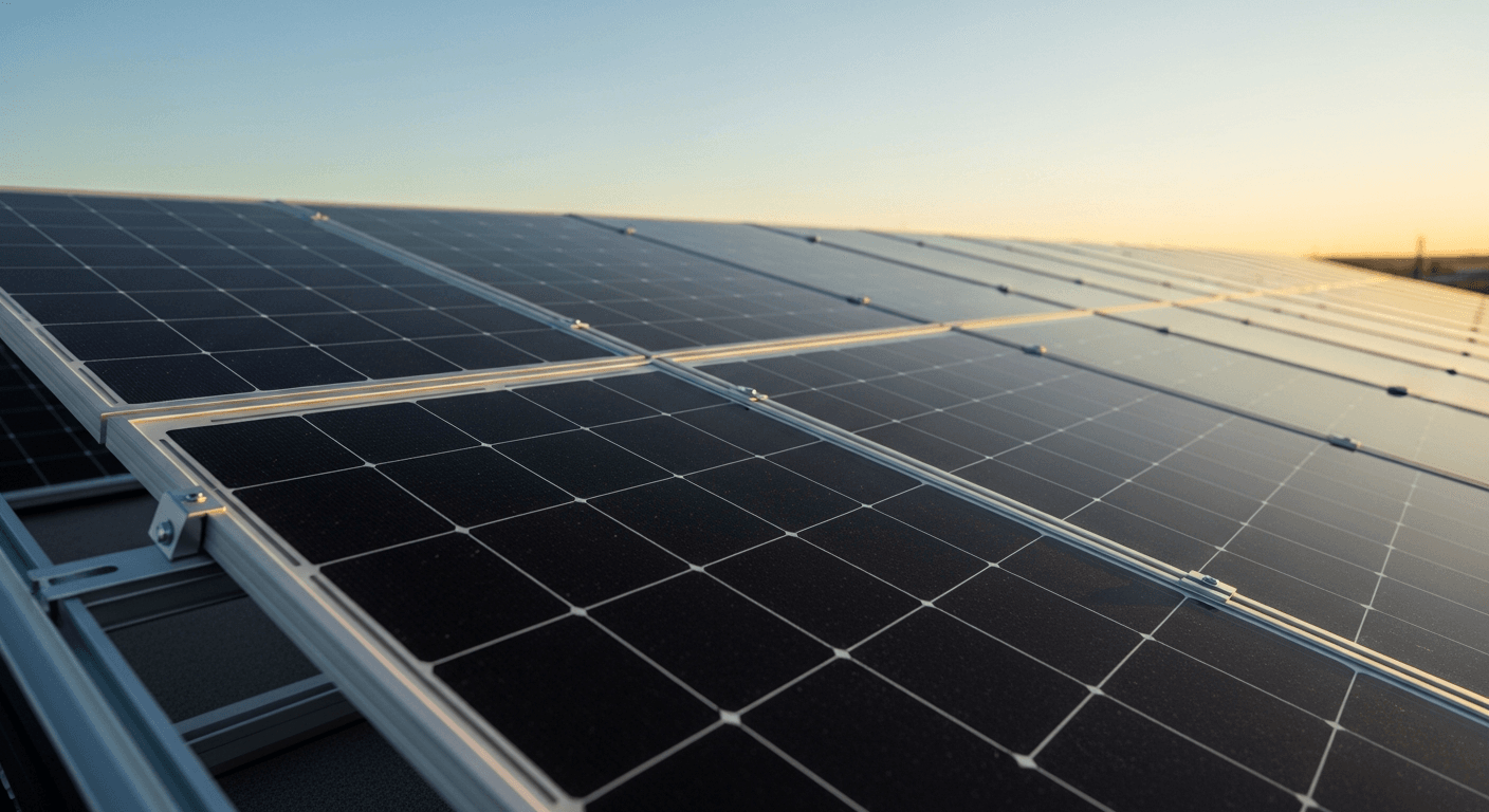
- Photovoltaic Panels: Standard high-quality monocrystalline PERC panels now consistently achieve efficiencies between 23% and 25%. Premium HJT and TOPCon modules are pushing 26% in commercial production, offering superior performance in low-light conditions and a better temperature coefficient (typically -0.25%/°C compared to -0.35%/°C for standard mono).
- Inverters: A Pure Sine Wave output is the mandatory standard, ensuring compatibility with sensitive electronics. Hybrid inverters, which manage inputs from solar, battery, and the grid, boast efficiencies exceeding 98%. Total Harmonic Distortion (THD) must be below 3% to ensure clean power. Microinverters and DC optimizers continue to offer panel-level optimization, ideal for complex roofs with shading issues.
- Charge Controllers: Maximum Power Point Tracking (MPPT) technology is ubiquitous, with operational efficiencies of 99% or higher. An MPPT controller constantly adjusts the electrical operating point of the PV array to extract the maximum available power, a critical function as solar irradiance and temperature fluctuate throughout the day.
- Battery Systems: LiFePO4 chemistry dominates the residential and commercial storage market. Key metrics for 2026 include a cycle life of 6,000-10,000 cycles at an 90% Depth of Discharge (DoD), a round-trip efficiency (RTE) of over 95%, and superior thermal stability, which mitigates fire risk compared to older NMC chemistries.
Load Calculation and System Sizing Strategy
Properly sizing a solar power station is an engineering imperative to ensure reliability and avoid premature system failure. The process is methodical:
1. Energy Audit & Load Calculation: The first step is to create a detailed load profile. List every AC and DC appliance, its power consumption in Watts, and its estimated daily hours of operation. The sum of (Watts × Hours) for all devices gives the total daily energy requirement in Watt-hours (Wh). A 25% safety margin is added to account for system losses and future load growth.
2. Battery Bank Sizing: The battery bank must store enough energy to cover nighttime usage and days of autonomy (low-sun days). The required capacity in Ampere-hours (Ah) is calculated as:
Total Daily Wh / (Battery Bank Voltage × DoD) = Required Ah.
For a 5,000 Wh daily load on a 48V system with 90% DoD, the calculation is: 5000 / (48 × 0.90) ≈ 116 Ah.
3. PV Array Sizing: The solar array must generate enough energy to power daily loads and fully recharge the battery bank. The required array size in Watts is determined by:
Total Daily Wh / (Peak Sun Hours × System Derating Factor) = Required PV Wattage.
“Peak Sun Hours” is a location-specific value representing the equivalent hours of 1000 W/m² solar irradiance. The derating factor (typically 0.77-0.85) accounts for voltage drop, dirt, temperature losses, and component inefficiencies.
4. Inverter Sizing: The inverter must be sized for two criteria. Its continuous power rating (in Watts) must exceed the total power of all loads that could run simultaneously. Its surge rating must be high enough to handle the inrush current from inductive loads like motors in refrigerators or pumps. A high-frequency (HF) or low-frequency (LF) transformer design will dictate its surge capability.
Engineering Specifications & Innovations for Your Solar Power Station
The 2026 market is characterized by both highly integrated, user-friendly systems and deeply customizable component-based solutions. Leading brands are pushing the boundaries of power density, modularity, and smart control, while material science innovations promise the next leap in PV efficiency.
Brand-Specific Technology Ecosystems
EcoFlow & Bluetti: These brands excel in creating powerful, modular “plug-and-play” solar power station ecosystems. The EcoFlow DELTA Pro Ultra and Bluetti EP900 systems exemplify this trend. They feature stackable LiFePO4 battery packs, allowing users to scale capacity from a few kWh to over 20 kWh. Their integrated hybrid inverters deliver massive outputs (7kW+ continuous) and can be paralleled for even more power, capable of running an entire home, including 240V appliances like central air conditioners.
Victron Energy: Representing the pinnacle of professional-grade, customizable systems, Victron is the choice for robust off-grid and marine applications. Their ecosystem is built around core components like the MultiPlus-II inverter/charger, SmartSolar MPPT charge controllers, and the Cerbo GX system controller. This modularity allows engineers to design highly specific and resilient systems. The power of the Victron Remote Management (VRM) portal provides unparalleled remote monitoring and diagnostic capabilities.
Tesla Powerwall 3: The Powerwall 3, launched in late 2024, represents a significant evolution in grid-tied energy storage. It integrates a 11.5 kW solar inverter directly into the 13.5 kWh battery unit, simplifying installation and improving round-trip efficiency for DC-coupled solar. While operating within Tesla’s closed ecosystem, its software for storm prediction, time-of-use optimization, and seamless user experience remains a benchmark for the industry.
Next-Generation Cell Materials: Perovskite & Tandem Cells
While silicon remains dominant, the most exciting frontier in PV technology is perovskite. Perovskite solar cells use a material with a specific crystal structure that is remarkably effective at converting light to electricity. Their key advantages are the potential for very high efficiencies (lab records exceed 33%) and low-cost, high-throughput manufacturing methods like roll-to-roll printing.
The most commercially promising application for 2026 and beyond is the Perovskite-on-Silicon Tandem Cell. By layering a thin, semi-transparent perovskite cell on top of a traditional silicon cell, the tandem structure can capture a much broader spectrum of light. The perovskite layer efficiently absorbs high-energy blue light, while the lower-energy red and infrared light passes through to be absorbed by the silicon layer. This approach shatters the single-junction Shockley-Queisser limit, with commercial tandem panels expected to reach efficiencies of 28-30% by the end of the decade.
Technical Comparison of 2026 Solar Power Station Kits
Choosing the right system depends on specific engineering requirements, from power output to ecosystem flexibility. The following table compares five leading solutions representative of the 2026 market.
| Model/System | Type | Battery Chemistry | Capacity (Expandable) | Inverter Output (Cont./Peak) | Max PV Input | Key Feature |
|---|---|---|---|---|---|---|
| EcoFlow DELTA Pro Ultra | Modular Integrated | LiFePO4 | 6 kWh – 90 kWh | 7.2kW / 10.8kW (240V) | 5.6 kW (expandable to 16.8 kW) | High power density and extreme modularity. |
| Bluetti EP900 + B500 | Modular Split-Phase | LiFePO4 | 9.9 kWh – 39.6 kWh | 9kW / 13.5kW (240V) | 9 kW | Seamless grid-tie and off-grid switching. |
| Victron Custom Build | Component-Based | LiFePO4 (3rd Party) | Custom (5 kWh – 100+ kWh) | Custom (e.g., 8kW / 16kW per unit) | Virtually unlimited | Unmatched customization and remote diagnostics. |
| Tesla Powerwall 3 | Grid-Tied Integrated | NMC/LiFePO4 (Varies) | 13.5 kWh (stackable) | 11.5kW / 22kW | 11.5 kW (DC-coupled) | Integrated solar inverter and superior software. |
| Anker SOLIX F3800 | Portable/Home Hybrid | LiFePO4 | 3.84 kWh – 53.8 kWh | 6kW / 9kW (240V) | 4.8 kW | Direct EV charging capability via NEMA 14-50. |
Safety, Standards, and Installation Protocols
A high-power solar power station is an electrical generation plant attached to a home. As such, adherence to safety codes and standards is not optional; it is a fundamental requirement of a professional installation. This ensures the safety of inhabitants, first responders, and utility line workers.
NEC Codes and Rapid Shutdown
The National Electrical Code (NEC), particularly Article 690 (Solar Photovoltaic Systems) and Article 705 (Interconnected Electric Power Production Sources), governs the installation. A critical provision is NEC 690.12: Rapid Shutdown. This code requires a means to rapidly de-energize the DC conductors from the PV array. The goal is to create a safe zone for firefighters on the roof by reducing the voltage in conductors outside the array boundary to under 80 volts within 30 seconds. This is typically achieved using module-level power electronics (MLPE) like microinverters or DC optimizers.
Ingress Protection (IP) Ratings
IP ratings are crucial for ensuring the longevity and safety of outdoor components. The rating consists of two digits: the first for solids (0-6) and the second for liquids (0-9). For a solar installation, key ratings include:
- IP65: Components are dust-tight and protected from low-pressure water jets from any direction. This is the minimum rating for outdoor-mounted junction boxes and inverters.
- IP67: Components are dust-tight and can withstand temporary immersion in water up to 1 meter for 30 minutes. This is essential for PV connectors (e.g., MC4) and any equipment in areas prone to temporary flooding.
Fire Safety and Thermal Management
Battery safety is paramount. Modern LiFePO4 batteries are inherently more stable than older lithium-ion chemistries, but proper installation is still vital. All energy storage systems (ESS) must be certified to UL 9540. This standard subjects the entire system, including the batteries, inverter, and controls, to rigorous safety testing. Inverters must also be certified to UL 1741, which covers grid-interconnection safety. Proper ventilation of battery enclosures is critical to prevent heat buildup and the risk of thermal runaway. Furthermore, all overcurrent protection devices (fuses and circuit breakers) in the DC portion of the system must be specifically DC-rated, as DC arcs are more difficult to extinguish than AC arcs.
Operational Pre-Installation Checklist
A successful installation begins with meticulous planning. Before purchasing equipment or drilling a single hole, complete this engineering pre-installation checklist to ensure a smooth, compliant, and efficient project.
- Structural Analysis: Commission a structural engineering report to confirm your roof can support the dead load of the PV array and associated hardware, plus live loads like snow and wind.
- Shade Analysis: Perform a detailed shade analysis using a tool like a Solar Pathfinder or software modeling. Identify any obstructions (trees, chimneys) and quantify their impact on annual energy production.
- Utility and AHJ Verification: Contact your local utility to understand their net metering or interconnection agreement policies. Check with your Authority Having Jurisdiction (AHJ) for permitting requirements, setback rules, and any local amendments to the NEC.
- Component Specification: Based on your load profile and site analysis, specify the required PV array wattage, battery capacity (kWh), and inverter power (kW). Select components that are UL-listed and compatible.
- Electrical System Assessment: Evaluate your home’s main electrical service panel. Ensure there is sufficient capacity and physical space for the new breakers required for the solar and battery system. Plan the conduit runs from the array to the inverter and from the inverter to the main panel.
– Load Profile Calculation: Complete a comprehensive energy audit to determine your exact daily Watt-hour (Wh) requirement. This is the foundation for sizing all other components.
Advanced Engineering FAQ
What is the engineering difference between AC-coupling and DC-coupling a battery?
In a DC-coupled system, DC power from the solar panels is fed through a charge controller directly to the battery bank. The inverter then draws from the battery to create AC power for the home. This is highly efficient for off-grid systems as the energy is stored with only one inversion step. In an AC-coupled system, solar power first goes through a grid-tie inverter to become AC power. To charge a battery, this AC power is then converted back to DC by a battery-based inverter/charger. This involves an extra conversion step, leading to slightly lower round-trip efficiency, but it is easier to retrofit onto existing grid-tie solar installations.
How does the temperature coefficient of a PV panel impact real-world energy yield?
The temperature coefficient, measured in %/°C, quantifies how much a panel’s power output decreases for every degree Celsius above the standard test condition temperature of 25°C (77°F). A panel with a coefficient of -0.35%/°C will lose 0.35% of its maximum power for each degree rise. On a hot roof where cell temperatures can reach 65°C (a 40°C rise), this results in a 14% power loss (40 × 0.35). Panels with a better (less negative) coefficient, like HJT panels at -0.25%/°C, would only lose 10% in the same conditions, yielding significantly more energy over the system’s lifetime.
Why is a Pure Sine Wave inverter critical for a modern solar power station?
A Pure Sine Wave inverter produces an AC waveform that is identical to or cleaner than the power supplied by the utility grid. This is critical for the proper and safe functioning of modern electronics, which include microprocessors and sensitive circuits. In contrast, older Modified Sine Wave inverters produce a blocky, stepped waveform that can cause issues like buzzing in audio equipment, malfunctions in medical devices, and premature failure in appliances with AC motors or timers. For a reliable solar power station, a Pure Sine Wave inverter is non-negotiable.
Can I oversize my PV array relative to my inverter’s rating, and what are the benefits?
Yes, this practice is known as “inverter clipping” or designing with a high DC-to-AC ratio (e.g., 1.25 to 1.5). The benefit is increased energy harvest during the “shoulder” hours of the day (early morning and late afternoon) and on overcast days. While the inverter will “clip” or cap the power output at its maximum rating during peak sun hours around noon, the total energy generated throughout the day is often significantly higher. This is a common and effective design strategy to maximize the return on investment of a solar installation.
What are the key considerations for integrating an EV charger with a residential solar power station?
First, the inverter’s continuous output and the main service panel must be able to handle the high, sustained load of a Level 2 EV charger (typically 7kW to 11kW). Second, smart integration is key. A “solar-aware” EV charger can communicate with the solar power station’s controller to modulate its charging speed. This allows it to prioritize using surplus solar energy for charging, minimizing grid consumption. For off-grid scenarios, this load management is essential to prevent depleting the battery bank too quickly.
In conclusion, the design and installation of a solar power station in 2026 is a task of precision engineering. From selecting advanced HJT panels and LiFePO4 batteries to ensuring strict adherence to NEC and UL safety standards, every decision impacts the system’s performance, longevity, and safety. By embracing a holistic, data-driven approach, homeowners and engineers can deploy powerful, resilient energy solutions that provide true independence. The future of personal energy is not just about generation, but about intelligent storage and management, a domain where the modern solar power station reigns supreme.
📥 Associated Resource:

El Kouriani Abde Civil Engineer & Founder of SolarKiit
El Kouriani Abde is a seasoned Civil Engineer and Project Manager with over 21 years of field experience. As the founder and publisher of SolarKiit.com, he leverages his deep technical background to simplify complex renewable energy concepts. His mission is to provide homeowners and professionals with accurate, engineering-grade guides to maximize their solar investments and achieve energy independence.