Ultimate Guide: Residential Solar Power Station: System Architecture & Sizing
Solar Power Station for Home: The Ultimate 2026 Guide to System Architecture & Sizing
The acquisition of a solar power station for home use marks a fundamental shift in a homeowner’s relationship with energy. You are no longer a passive consumer subject to grid volatility and escalating utility rates; you become a prosumer, an active participant in your own energy ecosystem. As we advance towards 2026, this transition is not merely a trend but a technical and financial imperative. The grid infrastructure is aging, extreme weather events are increasing in frequency, and the economic case for energy independence has never been stronger.
At SolarKiit, our engineering mandate, detailed further on our About page, is to empower prosumers with the technical knowledge to not just purchase, but to master their energy future. This guide is not a superficial overview. It is a definitive technical reference, a deep dive into the physics, system architecture, and engineering mathematics required to correctly specify and deploy a residential solar power station.
We will benchmark the core components, dissect the regulatory framework, and provide the quantitative tools to optimize your investment. This is the blueprint for achieving true energy resilience, moving beyond simple backup to a fully integrated Ultimate Guide: Battery Storage System for Home | Top 2026 Models & Buyer’s Guide | SolarKiit that serves as the heart of a modern, intelligent household.
The Core Physics: From Photon to Electron
Understanding a solar power station requires moving beyond marketing specifications and into the fundamental principles of physics and chemistry. The entire system is a multi-stage energy conversion and storage device. Its performance is dictated not by magic, but by quantum mechanics, electrochemistry, and power electronics working in a calibrated synergy.
Photon Harvesting & The Photovoltaic Effect
At the quantum level, a solar panel is a semiconductor device engineered to exploit the photovoltaic effect. The process begins when a photon—a particle of light from the sun—strikes a silicon atom within the photovoltaic cell. For this to generate electricity, two conditions must be met: the photon’s energy must exceed the silicon’s ‘band gap’ energy (approximately 1.12 electron-volts), and the resulting excited electron must be directed into a circuit.
This is achieved by doping the silicon. One layer is doped with phosphorus (n-type), creating a surplus of free electrons, while the adjacent layer is doped with boron (p-type), creating ‘holes’ or electron vacancies. The interface between these layers, the p-n junction, establishes a powerful electric field. When a photon liberates an electron, this field prevents it from simply recombining with a hole; instead, it is swept towards the n-type layer and into the external circuit, creating a flow of direct current (DC).
The theoretical maximum efficiency of a single-junction silicon cell, known as the Shockley-Queisser Limit, is around 33.7%. In practice, real-world efficiencies are lower due to factors like recombination, thermalization losses, and material impurities. However, engineering advancements have pushed top-tier commercial panels to now exceed 23% efficiency, as verified by the NREL Solar Efficiency Standards.
The Chemistry of Storage: LiFePO₄ Intercalation
The DC electricity generated is useless without a means to store it for use after sunset or during an outage. This is the domain of the battery, and for modern residential systems, Lithium Iron Phosphate (LiFePO₄) is the superior chemistry. Its safety and longevity are rooted in its electrochemical process.
A LiFePO₄ battery consists of a carbon-based anode, a LiFePO₄ cathode, and an electrolyte. During charging, lithium ions (Li+) migrate from the cathode to the anode, where they are embedded within the graphite’s structure in a process called intercalation. The iron phosphate’s olivine crystal structure is exceptionally stable, with strong covalent P-O bonds that resist breaking down even under high temperatures. This makes LiFePO₄ far less prone to thermal runaway compared to chemistries like Lithium Nickel Manganese Cobalt Oxide (NMC).
During discharge, the lithium ions de-intercalate from the anode and return to the cathode, releasing electrons to power your home. This robust chemical process allows for thousands of deep discharge cycles with minimal capacity degradation, which is a critical factor for long-term ROI. For a deeper analysis, our French-speaking engineers can consult our guide on Batteries Solaires LiFePO4 : Le Guide Ultime pour l’Énergie Renouvelable.
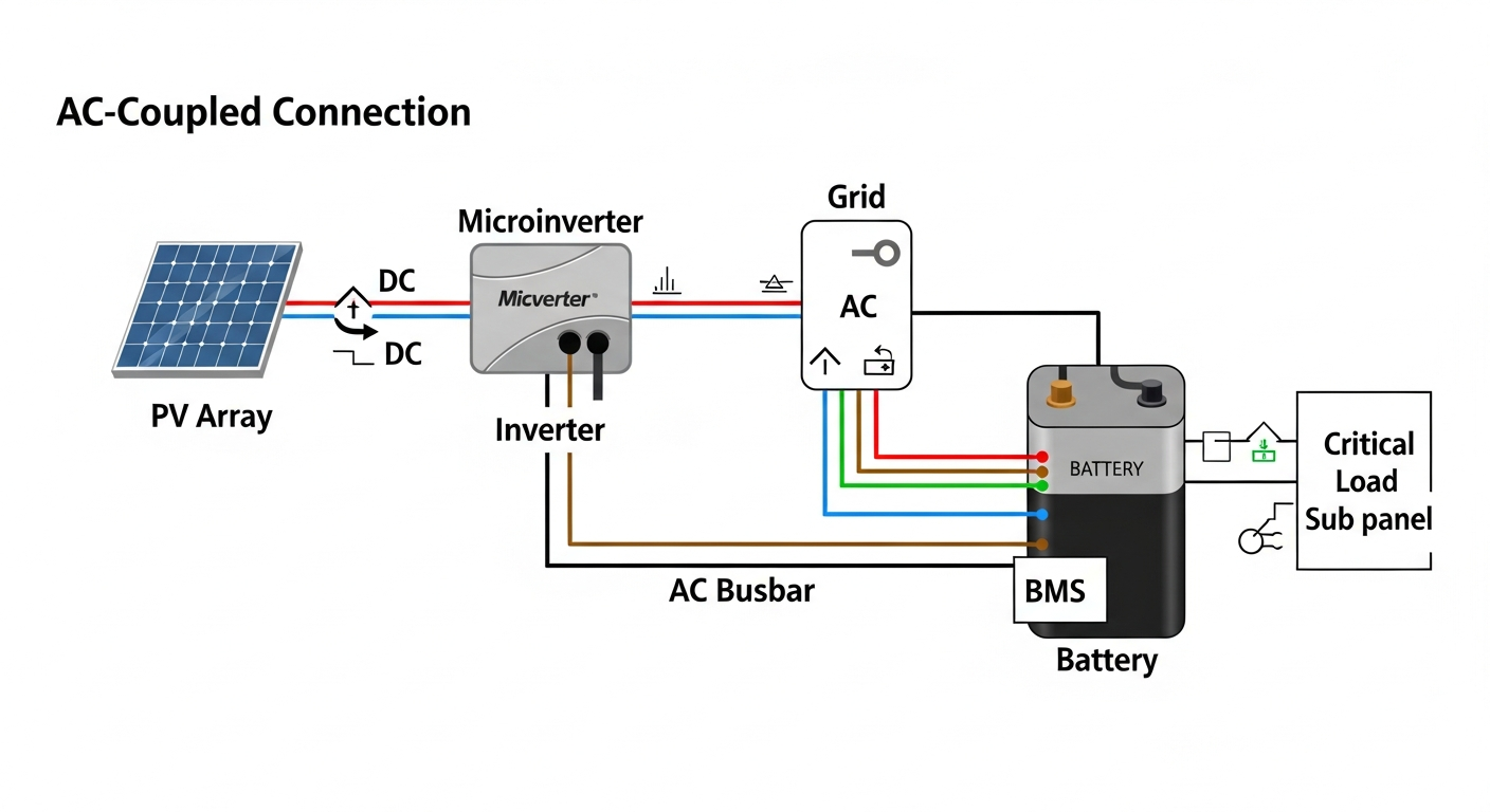
Component Synergy: The Digital Handshake in a Solar Power Station for Home
A solar power station is more than a collection of parts; it’s a cohesive system where each component’s performance is intrinsically linked to the others. The “digital handshake” between the Battery Management System (BMS), the Maximum Power Point Tracking (MPPT) charge controller, and the inverter determines the system’s overall efficiency, safety, and lifespan.
The Triumvirate: BMS, MPPT, and Inverter
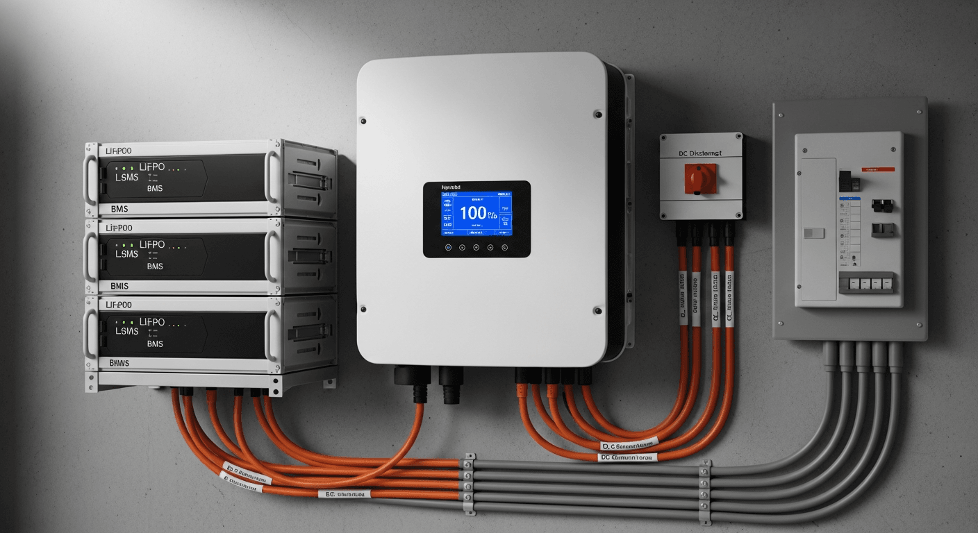
- Battery Management System (BMS): The BMS is the brain and guardian of the battery pack. It is not an optional component; it is a mission-critical safety and performance device. Its primary functions are to monitor the state of charge (SoC), state of health (SoH), and temperature of individual cell groups. It prevents over-charging, over-discharging, over-current, and short circuits by controlling a series of contactors. A sophisticated BMS also performs cell balancing, ensuring all cell groups are at an equal voltage, which is crucial for maximizing usable capacity and extending the battery’s cycle life.
- Maximum Power Point Tracking (MPPT) Charge Controller: The output of a solar panel array is not constant; its voltage and current fluctuate with solar irradiance and temperature. The MPPT’s job is to be the perfect impedance match between the solar array and the battery. It continuously scans the array’s I-V (current-voltage) curve to find the “knee”—the point of maximum power output—and adjusts its internal DC-DC converter to operate the array at that precise voltage. This process can harvest up to 30% more power compared to older PWM (Pulse Width Modulation) controllers, especially in cold weather or low-light conditions.
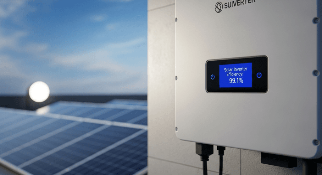
- Inverter: The inverter is the system’s translator, converting the low-voltage DC power from the battery into the 120/240V AC power that your home appliances use. The critical specification here is “pure sine wave” output. This clean, grid-quality waveform is essential for modern electronics, motors, and sensitive medical equipment. The inverter’s efficiency, detailed in our Solar Inverter Efficiency: The Ultimate Guide to Maximizing Your PV System’s Output & ROI, directly impacts how much stored energy is lost as heat during the conversion process.
These three components communicate constantly. The BMS tells the MPPT when to reduce or stop charging. The BMS communicates with the inverter to signal a low-voltage cutoff to protect the battery. A failure in this digital handshake can lead to catastrophic battery damage or, at best, a severely underperforming system.
Sizing Your System: The Engineering Mathematics of Energy Autonomy
Correctly sizing a solar power station is an engineering calculation, not a guess. Undersizing leads to frustrating power shortages, while oversizing wastes capital and yields diminishing returns. The process begins with a meticulous analysis of your home’s energy consumption, known as a load profile.
First, you must quantify your Total Daily Load in kilowatt-hours (kWh). This involves auditing every appliance, from the refrigerator’s baseload to the intermittent use of a microwave or well pump. For high-draw appliances with motors (like air conditioners or pumps), you must also account for Surge Capacity (also known as Locked Rotor Amps or LRA), which can be 3-7 times the running wattage. Your inverter must be rated to handle this momentary peak.
Next, determine your required Days of Autonomy—the number of consecutive cloudy days you want the system to operate without any solar input. For grid-tied backup, 1-2 days may suffice. For true energy independence, as seen in the Best Off-Grid Solar Kits of 2024: The Ultimate Guide to Energy Independence, 3-5 days is a more robust target.
The core formula to calculate required battery capacity (in Amp-hours) is:
Required Capacity (Ah) = (Total Daily Load (Wh) * Days of Autonomy) / (Battery DoD * System Voltage * Round-trip Efficiency)
- Total Daily Load (Wh): Your daily kWh usage multiplied by 1000.
- Days of Autonomy: Your desired number of backup days (e.g., 2).
- Battery DoD (Depth of Discharge): The percentage of the battery you plan to use. For LiFePO₄, 80-90% (0.8-0.9) is standard.
- System Voltage: The nominal voltage of your battery bank (e.g., 48V).
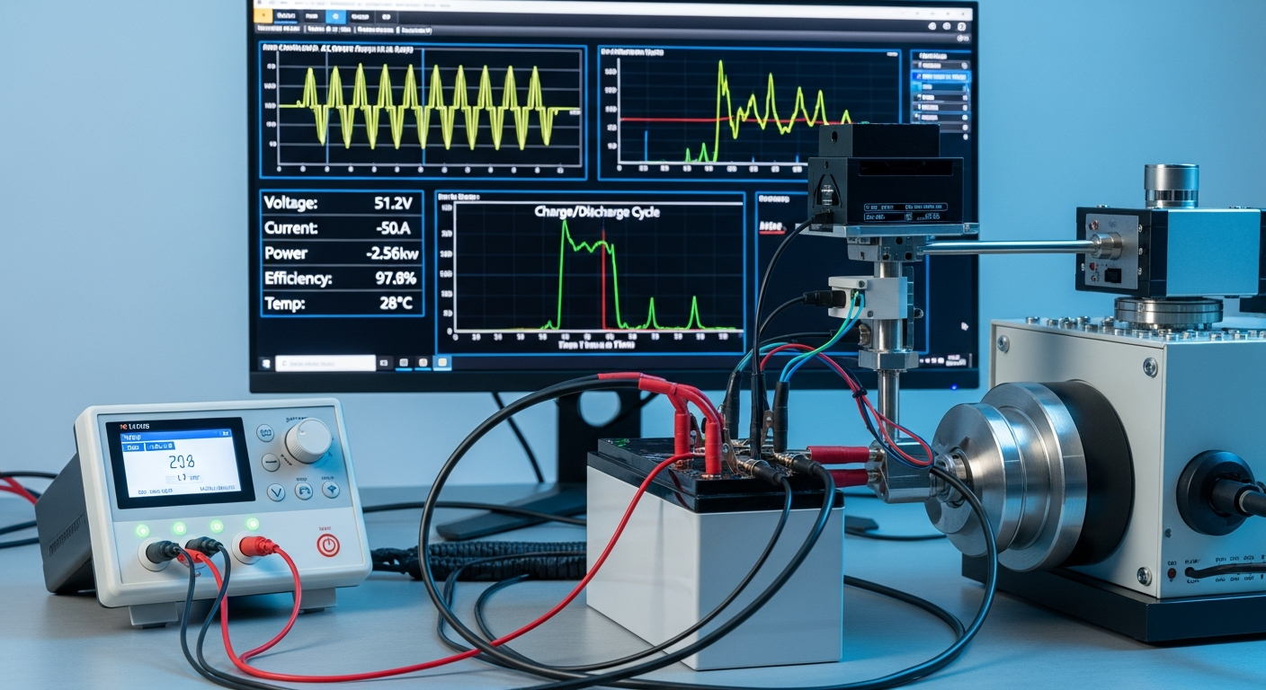
- Round-trip Efficiency: The energy lost in a charge/discharge cycle. For LiFePO₄ systems, this is typically 90-95% (0.9-0.95).
This calculation provides the minimum required battery capacity. The solar array must then be sized to replenish this daily usage and account for system losses, typically by calculating peak sun hours for your location.
2026 Benchmark: A Comparative Analysis of Leading Home Solar Power Stations
To provide a quantitative perspective, we’ve benchmarked five leading models anticipated for the 2026 market. The Levelized Cost of Energy (LCOE) is a critical metric, calculated as Total Lifetime Cost / Total Lifetime Energy Output, providing a true “apples-to-apples” cost per kWh.
| Model | Usable Capacity (kWh) | Continuous Output (kW) | Est. LCOE ($/kWh) | Cycle Life (Cycles @ 80% DoD) | Warranty (Years) |
|---|---|---|---|---|---|
| SolarKiit SK-15 | 15.0 | 7.6 | $0.11 | 8,000+ | 15 |
| Tesla Powerwall 3 | 13.5 | 11.5 | $0.14 | ~4,000 (Unlimited Cycles) | 10 |
| Enphase IQ Battery 5P | 5.0 | 3.84 | $0.13 | 6,000+ | 15 |
| FranklinWH aPower | 13.6 | 5.0 | $0.15 | ~4,000 (43 MWh Throughput) | 12 |
| Generac PWRcell | 18.0 (max config) | 9.0 | $0.16 | ~4,000 (75.6 MWh Throughput) | 10 |
Navigating the Regulatory Maze: NEC 2026, UL 9540, and Fire Safety Protocols
A technically sound system is worthless if it cannot be legally and safely interconnected. The regulatory landscape is complex, governed by a hierarchy of codes and standards designed to protect installers, homeowners, and first responders. Ignorance of these codes is not an excuse and can result in failed inspections, voided insurance, and significant danger.
Decoding NEC 2026 for Your Solar Power Station for Home
The NFPA 70: National Electrical Code (NEC) is the foundational document for all electrical installations in the United States. For a residential solar power station, two articles are paramount: Article 690 (Solar Photovoltaic Systems) and Article 706 (Energy Storage Systems). The 2026 revision cycle is expected to continue refining requirements for rapid shutdown, a safety feature that de-energizes conductors on the roof to protect firefighters.
NEC 706 dictates specific requirements for ESS installation, including ventilation, signage, and disconnecting means. Proper conductor sizing, overcurrent protection, and grounding are not suggestions; they are legally enforceable standards that must be verified by a licensed electrician, even in a DIY Solar Panel Installation: The Ultimate Guide for Homeowners in 2026 scenario.
The Gold Standard: UL 9540 and UL 9540A Compliance
While the NEC tells you how to install a system, Underwriters Laboratories (UL) standards certify that the equipment itself is safe. UL 9540 is the Standard for Energy Storage Systems and Equipment. A system listed to UL 9540 has been tested as a complete, integrated unit—including the battery, inverter, and controls—ensuring all components work together safely. This is far superior to using a collection of individually listed but uncertified components.
Furthermore, UL 9540A is the Test Method for Evaluating Thermal Runaway Fire Propagation. A system that has passed this large-scale test has proven that if a single battery cell fails, the fire will not cascade to adjacent cells or units. For any system installed inside a home or attached garage, UL 9540 listing and UL 9540A test data are non-negotiable safety benchmarks. Always verify these certifications with the manufacturer or through UL Solutions (Solar Safety) directly.
Fire Safety & Mitigation
Beyond certifications, physical installation practices are critical. Systems must be installed with mandated clearances from walls, ceilings, and other equipment to allow for heat dissipation and service access. The location must be protected from physical damage and extreme temperatures. The inherent chemical stability of LiFePO₄ provides a significant head start in fire mitigation, but it does not eliminate the need for proper engineering controls. This includes a robust BMS, correct fusing, and adherence to all manufacturer installation guidelines and local fire codes.
Advanced Engineering FAQ
1. Why is round-trip efficiency a more critical metric than nominal capacity for ROI?
Round-trip efficiency directly dictates how much of your harvested solar energy is actually available for use, fundamentally impacting the system’s lifetime value. A battery’s nominal capacity (kWh) is a static number, but its effective value is diminished by every percentage point lost during the charge and discharge cycle. Consider two 10kWh batteries: one with 95% round-trip efficiency and another with 85%.
- To deliver 8.5 kWh to your home, the 95% efficient battery needs to be charged with ~8.95 kWh (8.5 / 0.95).
- The 85% efficient battery needs to be charged with 10 kWh (8.5 / 0.85).
Over a 15-year lifespan with daily cycling, this 10% efficiency gap translates to thousands of kWh of solar generation that are simply wasted as heat. This wasted energy represents a direct financial loss, as it could have been used to offset grid purchases or sold back to the utility. Therefore, a slightly smaller but more efficient system can offer a superior ROI. This concept is a core tenet of our Ultimate Guide: Understanding Round-Trip Efficiency in High-Voltage Energy Storage: A 2024 Engineer’s Guide | SolarKiit.
2. How does the inverter’s waveform (pure sine wave vs. modified) impact sensitive electronics and overall system performance?
A pure sine wave inverter is mandatory for modern homes because its clean output is identical to grid power, ensuring compatibility and preventing damage to sensitive electronics. A modified sine wave is a crude, stepped approximation of a true sine wave. While it can power simple resistive loads like incandescent bulbs, it causes significant problems for other devices.
- Electronics: Devices with AC-DC power bricks (laptops, TVs, LED drivers) can overheat and fail prematurely.
- Motors: Inductive loads like refrigerator compressors and fans will run hotter, less efficiently, and make an audible “buzz,” drastically shortening their lifespan.
- Medical Equipment: Devices like CPAP machines or oxygen concentrators require a pure sine wave for correct and safe operation.
Using a modified sine wave inverter is a false economy that puts thousands of dollars of appliances at risk. A high-quality pure sine wave inverter is a foundational component of a reliable residential power system.
3. What is the engineering rationale behind high-voltage (HV) vs. low-voltage (LV) battery systems in a residential context?
High-voltage (400V-class) battery systems offer superior efficiency and lower installation costs compared to traditional low-voltage (48V) systems. The primary reason is rooted in basic electrical physics: Power = Voltage × Current. To deliver the same amount of power, a higher voltage system requires significantly less current.
- Higher Efficiency: Lower current dramatically reduces resistive losses (I²R losses) in the wiring and components. This means more of the energy stored in the battery makes it to your appliances.
- Lower Cost: The smaller current allows for much thinner, less expensive copper wiring between the battery and the hybrid inverter. This reduces material costs and simplifies the installation process.
- Direct DC Coupling: HV systems often allow for more efficient “DC-to-DC” coupling from the solar panels directly to the battery, bypassing an extra DC-AC-DC conversion step and its associated energy losses.
While 48V LV systems are proven and reliable, the industry is standardizing on HV architecture for new residential installations due to these clear engineering advantages.
4. Can you explain the concept of “stacking” systems for scalability and the role of the master/slave BMS communication protocol?
Stacking allows for modular capacity expansion by connecting multiple battery units, which requires a sophisticated master/slave BMS protocol to operate as a single, cohesive bank. You cannot simply wire multiple “smart” batteries in parallel and expect them to work. This would create a scenario where multiple BMS units fight for control, leading to imbalanced charging and potential safety hazards. In a properly engineered stacked system:
- One battery unit is designated as the “master.” Its BMS takes overall command of the entire bank.
- The master BMS consolidates the data from all slaves to get a complete picture of the total state of charge, state of health, and temperature profile of the entire system.
- It then communicates with the inverter and charge controller on behalf of the entire bank, ensuring synchronized and safe operation.
– The other units are designated as “slaves.” Their BMS boards monitor their individual cells but report all data up to the master and follow its commands.
This architecture is essential for safely scaling a system from a small portable power station to a full-home solution.
5. Beyond basic sizing, how do you factor in Depth of Discharge (DoD) and temperature degradation curves to accurately project a battery’s 10-year lifespan?
Accurate lifespan projection requires moving beyond the warranty’s cycle count and modeling the combined impacts of DoD and temperature using manufacturer-provided degradation data. A battery’s warranty of “6,000 cycles” is typically rated at a specific DoD (e.g., 80%) and temperature (e.g., 25°C). Real-world conditions are never this perfect.
- Depth of Discharge (DoD): There is a non-linear relationship between DoD and cycle life. Consistently discharging to 100% will degrade a battery much faster than cycling it to only 70%. A shallower average DoD significantly extends lifespan.
- Temperature: Both high and low temperatures accelerate degradation. High temperatures increase the rate of parasitic chemical reactions, while charging at low temperatures can cause lithium plating, permanently reducing capacity.
To accurately project performance, engineers use degradation curves (which should be requested from the manufacturer) to model capacity fade over time based on the expected usage patterns and climate of the installation site. This provides a much more realistic expectation of the battery’s end-of-life capacity than relying on a single marketing number. For a personalized analysis, we encourage you to Contact our engineering team. This guide is for informational purposes; please review our Privacy Policy. The ultimate goal is to correctly engineer and install a reliable solar power station for home.
📥 Associated Resource:

El Kouriani Abde Civil Engineer & Founder of SolarKiit
El Kouriani Abde is a seasoned Civil Engineer and Project Manager with over 21 years of field experience. As the founder and publisher of SolarKiit.com, he leverages his deep technical background to simplify complex renewable energy concepts. His mission is to provide homeowners and professionals with accurate, engineering-grade guides to maximize their solar investments and achieve energy independence.