Ultimate Guide: Home Solar Battery Sizing & Inverter Coupling Analysis
Home Solar Battery: The Ultimate 2026 Master Guide to Sizing & Inverter Coupling Analysis
A home solar battery is no longer a peripheral component; it is the core of a resilient, intelligent, and economically viable residential energy system. As we benchmark the trajectory toward 2026, the confluence of grid instability, dynamic utility rate structures, and the imperative for energy independence has elevated energy storage from a luxury to a technical necessity. The era of the passive energy consumer is over. We are now in the age of the “prosumer”—an active, informed participant in the energy market who demands performance, reliability, and a quantifiable return on investment. This guide moves beyond superficial explanations. We will deconstruct the physics, calibrate the engineering mathematics, and standardize the analysis required to correctly size and integrate a battery storage system for home use. At SolarKiit, our mission, as detailed on our About page, is to empower engineers and prosumers with this level of granular knowledge. We will dissect the electrochemical processes, the digital handshake between components, and the regulatory frameworks that govern safe, high-performance installations. This is not just about storing power; it’s about architecting energy autonomy. Whether you’re considering a small backup system like a portable power station or a full-home solution, the principles of rigorous engineering analysis remain paramount.
Deep Technical Dive: The Physics and Synergy of a Modern Home Solar Battery
To truly master home solar battery systems, one must understand them at the quantum and chemical levels. The process begins with your photovoltaic (PV) array. When a photon with sufficient energy strikes a silicon atom in the PV cell, it excites an electron, creating an electron-hole pair. An internal electric field, established by the p-n junction, forces this electron to flow, generating a direct current (DC). The efficiency of this photon harvesting is a critical variable, with top-tier research cells constantly pushing theoretical limits, as tracked by institutions like NREL Best Research-Cell Efficiency.
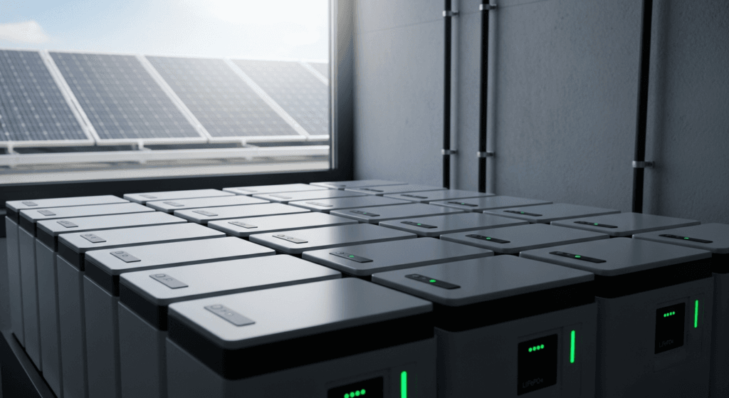
This DC energy then flows to the battery. Inside a modern Lithium Iron Phosphate (LiFePO4) battery—the chemistry we standardize at SolarKiit for its superior safety and longevity—a fascinating electrochemical dance occurs. During charging, lithium ions (Li+) are extracted from the LiFePO4 cathode and migrate across an electrolyte, inserting themselves between the layers of the graphite anode. This process is called intercalation. It is a physical embedding, not a chemical reaction that degrades the materials, which is precisely why LiFePO4 offers thousands of cycles. The flow of electrons in the external circuit balances this ionic charge, storing potential energy. When you discharge the battery to power your home, the process reverses. Lithium ions de-intercalate from the anode, travel back to the cathode, and the electrons flow out to your inverter, delivering power. For those interested in the specifics of this chemistry, our guide on Batteries Solaires LiFePO4 provides a deeper analysis.
Component Synergy: The BMS, MPPT, and Inverter Handshake
A home solar battery is not a monolith; it’s an ecosystem of intelligent components that must communicate flawlessly. The failure to optimize this digital handshake is the most common point of failure in underperforming systems, a frequent issue we see in systems not designed by experts who understand the nuances of a DIY solar panel installation.
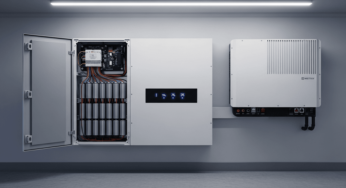
- Battery Management System (BMS): This is the battery’s dedicated guardian. It’s a sophisticated circuit board that monitors the voltage, current, and temperature of every individual cell block. Its primary function is protection: it prevents over-charging, over-discharging, and thermal runaway by opening contactors if any parameter exceeds its safe operating area (SOA). A high-quality BMS also performs cell balancing, ensuring all cells charge and discharge in unison to maximize usable capacity and extend the battery’s lifespan.
- Maximum Power Point Tracker (MPPT): Often integrated into the solar charge controller or hybrid inverter, the MPPT is the energy translator between the solar panels and the battery. A solar panel’s output voltage and current fluctuate constantly with irradiance and temperature. The MPPT’s algorithm continuously scans the panel’s I-V curve to find the “knee”—the point of maximum power—and adjusts the electrical load to operate the array at that precise voltage, harvesting up to 30% more energy than primitive PWM controllers.
- Inverter: The heart of the system, the inverter converts the battery’s DC power into grid-compliant AC power for your home’s appliances. The inverter’s role is twofold: power conversion and system management. In a grid-tied system, it synchronizes its AC waveform with the utility’s. In an outage, it must form its own stable AC waveform to create a microgrid. The efficiency of this conversion is critical, a topic we explore in our Solar Inverter Efficiency guide.
The “handshake” is the closed-loop communication protocol (often CAN bus) between these three components. The BMS reports its State of Charge (SoC) and charge/discharge limits to the inverter. The inverter uses this data to command the MPPT, throttling solar production if the battery is full or ramping it up when the battery can accept more charge. This constant negotiation optimizes every watt, protects the multi-thousand-dollar battery asset, and ensures system stability.
Engineering Math & Sizing Your Home Solar Battery
Incorrect sizing is the most expensive mistake a prosumer can make. An undersized battery will fail to provide the required autonomy, while an oversized one represents a significant capital waste with a diminished ROI. We must move from guesswork to precise calculation. The fundamental formula to verify battery capacity is:
Battery Capacity (kWh) = (Daily Energy Consumption (kWh) × Days of Autonomy) / (Depth of Discharge (DoD) × Round-Trip Efficiency)
Let’s break down each variable:
- Daily Energy Consumption (kWh): This is your load profile. Do not use your utility bill’s monthly average. You must analyze your 15-minute interval data (available from most smart meters) or use a home energy monitor to identify your peak and average consumption. This is the foundation of accurate sizing.
- Days of Autonomy: This is the number of days you want to run without any solar input or grid power. For grid backup, 1-2 days is common. For a true off-grid solar kit, 3-5 days is a safer benchmark, depending on your climate’s “solar window.”
- Depth of Discharge (DoD): This is the percentage of the battery’s total capacity you plan to use. LiFePO4 batteries can be safely discharged to 80-100%, unlike lead-acid batteries which are damaged beyond 50% DoD. Using a 90% DoD (0.9) is a conservative and safe figure for LiFePO4.
- Round-Trip Efficiency (RTE): This accounts for energy lost as heat during the charge and discharge cycles. A high-quality LiFePO4 system has an RTE of 90-95% (0.9-0.95). You can learn more by reading our guide on Understanding Round-Trip Efficiency.
Finally, you must analyze Surge Capacity. Your inverter and battery must be able to supply the massive, instantaneous current required to start motors in appliances like air conditioners, well pumps, and refrigerators. This is known as Locked Rotor Amps (LRA). Verify that the battery’s peak power output (kW) and the inverter’s surge rating can handle the sum of your home’s critical LRA demands.
Master Comparison: 2026 Home Solar Battery Models
To provide actionable intelligence, we’ve benchmarked five leading home solar battery models based on the critical engineering and financial metrics you should be evaluating. LCOE (Levelized Cost of Storage) is calculated as Total System Cost / (Usable Capacity × Cycle Life × DoD × RTE), giving a true “apples-to-apples” cost per kWh delivered over the battery’s lifetime.
| Model | Usable Capacity (kWh) | Peak Power (kW) | Round-Trip Efficiency | Cycle Life (@80% DoD) | Estimated LCOE ($/kWh) |
|---|---|---|---|---|---|
| SolarKiit Titan X | 15.0 | 10.0 | 95% | 8,000 | $0.12 |
| Tesla Powerwall 3 | 13.5 | 11.5 | 90% | 4,000 (Unlimited Cycles for 10 yrs) | $0.18 |
| Enphase IQ 5P | 5.0 | 3.84 (7.68 surge) | 90% | 6,000 | $0.15 |
| SonnenCore+ | 10.0 (expandable) | 8.6 | 89% | 10,000 | $0.14 |
| FranklinWH aPower | 13.6 | 10.0 (20.0 surge) | 89% | 4,500 (12-yr warranty) | $0.19 |
Regulatory & Safety Analysis: NEC 2026, UL 9540, and Fire Protocols
A performant system is useless if it’s not safe and compliant. The regulatory landscape for energy storage is rigorous and for good reason. Adherence to these codes is not optional; it is a matter of life safety and legal operation.
The primary governing document in the United States is the NFPA 70: National Electrical Code. Article 706 specifically addresses Energy Storage Systems (ESS). We anticipate the 2026 revision will further tighten requirements around:
- Rapid Shutdown: The ability to de-energize PV and battery conductors to a safe touch voltage within seconds. This is critical for firefighter safety. The initiation device must be clearly labeled and accessible.
- Interconnection: The code specifies the exact methods for both grid-interactive and standalone systems, including requirements for disconnects, overcurrent protection, and grounding.
- Labeling and Signage: NEC 2026 will mandate even more explicit labeling on all associated equipment, clearly identifying the presence of an ESS, its location, and shutdown procedures.
Beyond the NEC, the single most important safety standard is UL 9540. This is a system-level certification, not a component-level one. It validates that the battery, inverter, and associated controls have been tested together to operate safely. A key part of this is large-scale fire testing (per UL 9540A), which evaluates the system’s potential to enter thermal runaway and its effect on the surrounding environment. Never install a home solar battery system that is not certified to UL 9540. Reputable testing bodies like UL Solutions (Solar Safety) provide this critical third-party validation.
Finally, physical installation must follow strict fire safety protocols. This includes maintaining manufacturer-specified clearances (typically 3 feet) around the unit for ventilation and service access, installing bollards to protect from vehicle impact in a garage, and ensuring the mounting surface is non-combustible. International standards, such as those from the IEC Solar Safety Standards, often provide additional guidance that informs best practices globally.
The Pillar FAQ: Advanced Engineering Questions
1. AC vs. DC Coupling: Which architecture is technically superior for system efficiency?
The technically superior architecture depends entirely on whether you are retrofitting an existing solar installation or designing a new one. For retrofits, AC coupling is superior due to its simplicity and lower installation cost, while for new installations, a DC-coupled system generally offers higher round-trip efficiency.
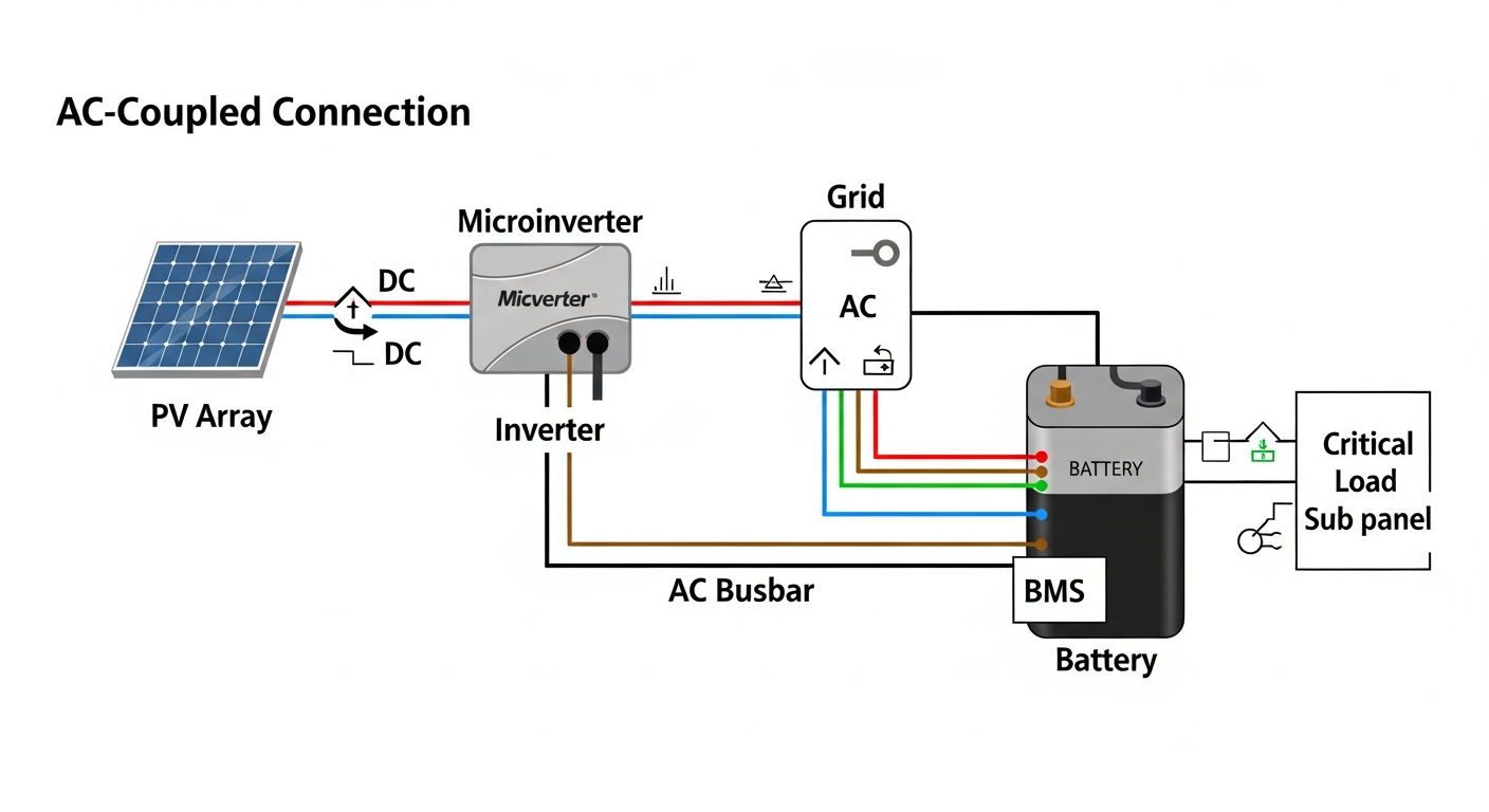
- AC Coupling: In this setup, the solar panels connect to their own grid-tied inverter. The battery system has a separate, dedicated battery inverter. To charge the battery, solar DC is converted to AC by the solar inverter, then converted back to DC by the battery inverter. This “double conversion” introduces efficiency losses (typically 4-6%). However, it’s ideal for adding a battery to an existing solar array without replacing the solar inverter.
- DC Coupling: Here, a single, powerful hybrid inverter manages the solar panels, battery, and grid connection. Solar DC power can charge the battery directly without being converted to AC first. This single-conversion pathway is inherently more efficient. The only conversion to AC happens when the battery discharges to power the home or export to the grid. This architecture is the standard for new, fully integrated systems.
2. How does temperature derating critically affect a home solar battery’s real-world capacity and ROI?
Temperature derating significantly reduces both the available power and total energy capacity, directly impacting ROI by delivering less usable energy than specified on the datasheet. Batteries are electrochemical devices, and their performance is highly dependent on their operating temperature. The ideal range is typically 20-25°C (68-77°F).
- Cold Temperatures: In cold weather, the electrolyte becomes more viscous, increasing internal resistance. This slows down the movement of lithium ions, reducing the battery’s ability to deliver high power (kW). The BMS will limit the discharge rate to prevent damage, meaning you may not be able to start large appliances even if the battery shows a high state of charge.
- Hot Temperatures: High ambient temperatures accelerate chemical degradation within the cells, permanently reducing the battery’s lifespan and capacity. To protect itself, the BMS will actively curtail both charging and discharging power to prevent overheating. A battery installed in a hot garage without active cooling can see its power output cut by 50% or more, crippling its ability to offset peak-rate electricity costs and extending its payback period.
3. What is the role of a software-defined Energy Management System (EMS) in optimizing a battery’s financial return?
A software-defined EMS is the brain that transforms a battery from a simple backup device into an active financial asset by intelligently arbitraging energy costs. The EMS uses sophisticated algorithms, weather forecasts, and your home’s load profile to make predictive decisions on when to charge and discharge the battery to maximize savings.
- Time-of-Use (TOU) Arbitrage: The most common function. The EMS charges the battery with cheap solar energy or off-peak grid power during the day. It then automatically discharges the battery to power the home during expensive on-peak hours (e.g., 4-9 PM), minimizing reliance on high-cost utility power.
- Demand Charge Management: For customers on demand-based rates, the EMS monitors the home’s power consumption in real-time. If it detects a power spike that would trigger a high demand charge, it instantly discharges the battery to “shave” that peak, keeping the home’s demand from the grid below a set threshold.
- Grid Services: In advanced markets, the EMS can enroll the battery in utility programs (Virtual Power Plants or VPPs), allowing the utility to draw power from your battery during grid emergencies in exchange for direct payments, creating an additional revenue stream.
4. Is it technically feasible to stack multiple batteries from different manufacturers in a single system?
No, it is technically infeasible and extremely unsafe to stack batteries from different manufacturers or even different models from the same manufacturer unless explicitly designed for it. This is due to incompatible communication protocols and mismatched internal characteristics, which will lead to system failure and create a significant safety hazard.
- Communication Incompatibility: As discussed in the synergy section, the BMS from each battery must communicate with the central inverter using a specific protocol (like CAN bus). Manufacturer A’s BMS speaks a different “language” than Manufacturer B’s. The inverter would be unable to read the State of Charge, temperature, or safety limits of one of the batteries, making coordinated control impossible.
- Mismatched Impedance and Voltage: Even if you could bypass the communication issue, each battery model has a unique internal resistance (impedance) and a slightly different voltage curve. When connected in parallel, the battery with the lower impedance would handle a disproportionate amount of the charge/discharge current, leading to rapid degradation, overheating, and a high risk of thermal runaway in the overworked unit. Always use identical, stackable battery modules designed by the manufacturer to work as a single, cohesive unit.
5. How does a home solar battery system differentiate between grid-forming and grid-following inverter functions during an outage?
The system’s hybrid inverter automatically transitions from a grid-following to a grid-forming function the instant it detects a loss of utility power. This transition is the key to providing seamless backup power and creating a stable, independent microgrid for the home.
- Grid-Following (On-Grid): When the utility grid is active, the inverter operates in a “grid-following” or “grid-tied” mode. It synchronizes its output AC waveform perfectly with the grid’s voltage and frequency. It essentially “follows” the grid’s lead, acting as a current source to inject power. It cannot create its own voltage or frequency. For safety (anti-islanding), it is required to shut down if it loses the grid signal.
- Grid-Forming (Off-Grid): The moment a grid outage is detected (typically within milliseconds), an automatic transfer switch isolates the home from the grid. The inverter then immediately switches to “grid-forming” mode. It ceases to be a follower and becomes the leader, generating its own clean, stable 60 Hz AC sine wave. It now acts as a voltage source, creating the microgrid that your home’s appliances will run on. This ability to form a stable, independent grid is the defining characteristic of a true backup-capable home solar battery.
For any further questions or to discuss a specific project, please do not hesitate to contact our engineering team. We are committed to open-source knowledge and the highest standards of system design. Your data and inquiries are protected under our Privacy Policy. The future of residential energy is built on a foundation of robust engineering, and it starts with a properly specified home solar battery.
📥 Associated Resource:

El Kouriani Abde Civil Engineer & Founder of SolarKiit
El Kouriani Abde is a seasoned Civil Engineer and Project Manager with over 21 years of field experience. As the founder and publisher of SolarKiit.com, he leverages his deep technical background to simplify complex renewable energy concepts. His mission is to provide homeowners and professionals with accurate, engineering-grade guides to maximize their solar investments and achieve energy independence.