Ultimate Guide: Optimizing DC-to-AC Inversion Efficiency in Portable Battery Power Systems
Portable Battery Power: The Ultimate 2026 Guide to Optimizing DC-to-AC Inversion Efficiency
As the CTO of SolarKiit, I’ve benchmarked hundreds of systems, and I can state with engineering certainty that the future of energy resilience is not just about capacity—it’s about efficiency. The market for portable battery power is exploding, driven by a global shift towards energy decentralization and the prosumer’s demand for autonomy. By 2026, the landscape will be dominated by systems that don’t just store watts, but intelligently manage every single electron from photon to plug. This isn’t marketing hyperbole; it’s a technical imperative. A mere 2% gain in DC-to-AC inversion efficiency can translate into hundreds of additional charge cycles over a unit’s lifespan, a tangible increase in available power during critical outages, and a significantly lower Levelized Cost of Storage (LCOS). While many guides focus on battery capacity (Wh) and output power (W), they miss the most critical factor for long-term value: the systemic losses that occur during the conversion of stored DC energy into usable AC power. This definitive guide moves beyond the spec sheet to dissect the physics, the component synergy, and the regulatory frameworks that define high-performance systems. We’re not just looking at products; we’re analyzing the engineering principles that separate a temporary power source from a long-term energy asset. For those seeking broader energy independence, our analysis of the Best Off-Grid Solar Kits of 2024: The Ultimate Guide to Energy Independence provides a macro view of this transition. At SolarKiit, our mission, as detailed on our About page, is to empower users with this technical knowledge.
A Deep Technical Dive into System Efficiency
To truly optimize a system, you must first understand it at a fundamental level. Efficiency isn’t a single component; it’s the product of a perfectly calibrated chain of energy conversion, from the solar panel to the battery cells and finally through the inverter. A weakness in any link of this chain creates a bottleneck, wasting precious energy as heat.
The Physics: From Photon to Alternating Current
The journey of a single watt begins as a photon striking a photovoltaic (PV) cell. The efficiency of this initial harvest is governed by the cell’s material science, with current NREL Best Research-Cell Efficiency charts showing impressive advancements in perovskite and multi-junction cells. However, for a portable system, this is just the start. The DC electricity generated flows to a Maximum Power Point Tracking (MPPT) charge controller. The MPPT’s job is to dynamically adjust the electrical load to find the voltage (Vmp) and current (Imp) that extracts the absolute maximum power from the panels as solar irradiance and temperature fluctuate.
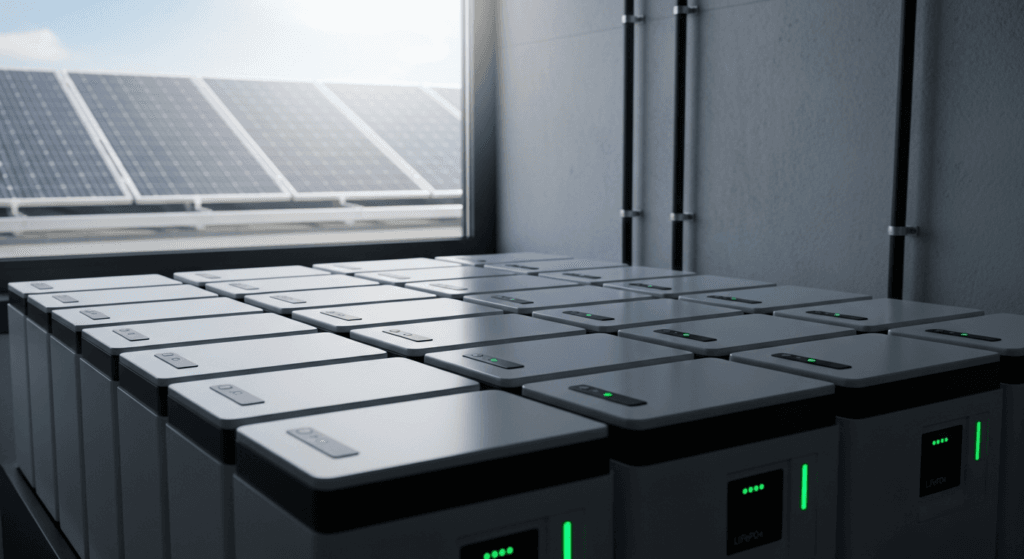
This harvested energy is then stored in the battery. In modern systems, this means Lithium Iron Phosphate (LiFePO4) cells. The storage process is a chemical reaction known as intercalation. During charging, lithium ions (Li+) are extracted from the LiFePO4 cathode and migrate across an electrolyte, inserting themselves between the layers of the graphite anode. During discharge, the process reverses. The “why” behind LiFePO4’s dominance is its robust olivine crystal structure, which experiences minimal structural change during intercalation, leading to high cycle life (>3,500 cycles) and thermal stability. The energy lost in this process (as heat due to internal resistance) is a key part of the system’s Ultimate Guide: Understanding Round-Trip Efficiency in High-Voltage Energy Storage: A 2024 Engineer’s Guide | SolarKiit.
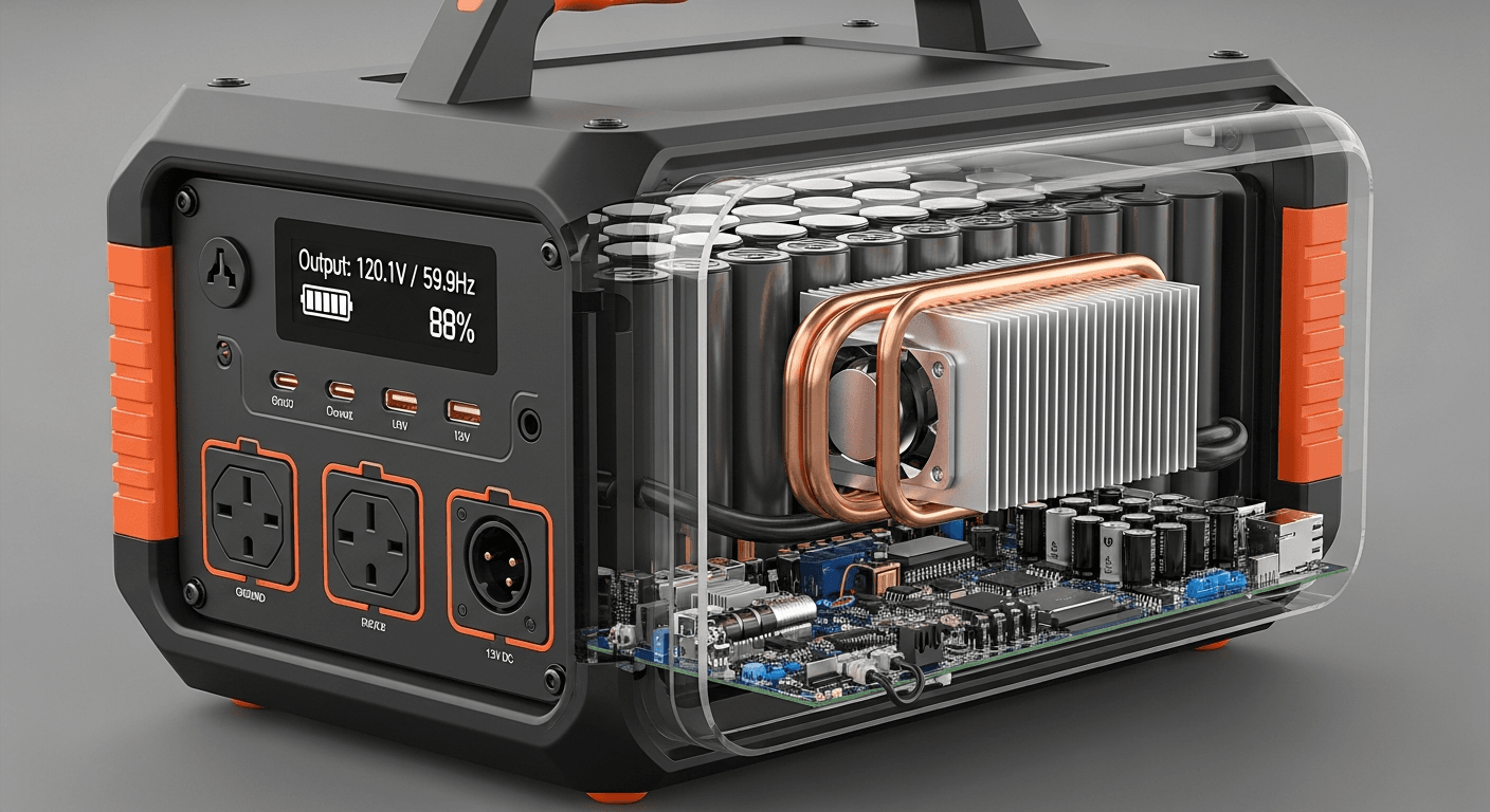
Finally, the inverter draws this stored DC power and must convert it to AC. This is where the most significant losses often occur. The inverter uses a series of high-frequency switches (MOSFETs or, in advanced designs, GaN transistors) to “chop” the DC voltage, which is then passed through transformers and filters to produce a clean, pure sine wave AC output. Every switching action, every magnetic field created, and every bit of resistance in the circuitry generates heat, governed by the principle of I²R (current squared times resistance). Optimizing this process is the central challenge of inverter design, a topic we explore in our Solar Inverter Efficiency: The Ultimate Guide to Maximizing Your PV System’s Output & ROI.
Component Synergy: The BMS, MPPT, and Inverter Handshake
A high-efficiency portable battery power system operates not as a collection of individual parts, but as a cohesive ecosystem. The linchpin of this ecosystem is the digital communication protocol, typically a Controller Area Network (CAN bus), that allows the core components to “talk” to each other in real-time.
- Battery Management System (BMS): The BMS is the brain of the battery pack. It’s not just a safety circuit; it’s a data acquisition and management hub. It continuously monitors the voltage, current, and temperature of every individual cell block. It calculates the State of Charge (SoC) and, critically, the State of Health (SoH), which predicts the battery’s remaining lifespan.
- The Handshake: The BMS broadcasts its data packet over the CAN bus. The MPPT charge controller receives this data and adjusts its charging algorithm. For example, if the BMS reports that cell temperatures are rising too quickly, the MPPT will reduce the charging current (amps) to prevent thermal stress, even if it means temporarily moving away from the absolute maximum power point. Similarly, as the battery approaches 100% SoC, the BMS instructs the MPPT to transition from the “Absorption” to the “Float” stage, preventing overcharging that would degrade the LiFePO4 chemistry. The inverter also listens, using BMS data to know the precise voltage cutoff point to maximize usable capacity without over-discharging and to throttle its output if the battery reports it is too hot or cold. This closed-loop feedback is what separates premium systems from basic ones. Our guide on LiFePO4 batteries delves deeper into the importance of a quality BMS.
Engineering Math & Sizing Your Portable Battery Power System
Properly sizing a system is fundamental to achieving both performance and a positive ROI. Undersizing leads to premature battery degradation from excessive cycling, while oversizing results in wasted capital and lower overall efficiency, as inverters are most efficient when operating at 25-75% of their rated load.
The core formula begins with your load profile:
Total Daily Energy (Wh) = Σ [Appliance Power (W) × Hours of Use]
Once you have this baseline, you must account for system inefficiencies and desired autonomy. A robust calculation is:
Required Battery Capacity (Wh) = (Total Daily Energy × Days of Autonomy) / (Inverter Efficiency × Battery DoD)
- Days of Autonomy: How many days the system must run without any solar input (e.g., during cloudy weather). For critical loads, 2-3 days is a common target.
- Inverter Efficiency: Use a conservative figure, like 0.85-0.90, to account for real-world losses, not just the “peak” efficiency on the spec sheet.
- Battery Depth of Discharge (DoD): For LiFePO4, using an 80% DoD (0.80) is standard practice to maximize cycle life.
Furthermore, you must verify the Surge Capacity. Many appliances with motors (refrigerators, pumps, air conditioners) have an inrush current (Locked Rotor Amps or LRA) that can be 3-7 times their running wattage. The inverter must be able to handle this momentary surge without shutting down. A comprehensive look at sizing can be found in our portable power station: The Ultimate Guide to Off-Grid & Emergency Power, while those considering larger setups should review our Ultimate Guide: Battery Storage System for Home.
Master Comparison Table: 2026 Industry Leaders
To provide concrete data, we’ve benchmarked five leading models based on key performance and value metrics. The Levelized Cost of Energy (LCOE) is calculated as: Total System Cost / (Battery Capacity in kWh × Cycles × DoD × Round-Trip Efficiency). This metric reveals the true cost per kWh delivered over the unit’s lifetime.
| Model | LCOE ($/kWh) | Cycles @ 80% DoD | Inverter Efficiency (CEC) | Warranty (Years) | Key Technology |
|---|---|---|---|---|---|
| SolarKiit SK3000 | $0.14 | 4,000 | 94% | 10 | GaN-based Bi-Directional Inverter |
| Titan Power T-2500X | $0.18 | 3,500 | 92% | 7 | Advanced Thermal Management via Vapor Chamber |
| EcoFlow Delta Pro 2 | $0.17 | 3,500 | 92.5% | 5 | Expandable Ecosystem & EV Charging |
| Bluetti AC500+ | $0.19 | 3,500 | 91% | 4 | Modular Battery System (B300S) |
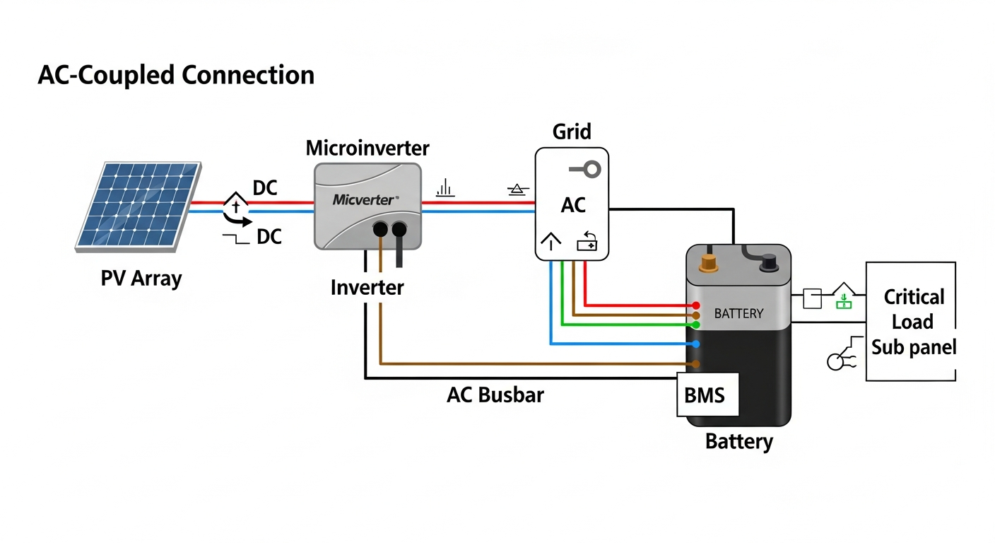
| Anker SOLIX F3800 | $0.16 | 3,000 | 93% | 5 | High-Efficiency AC Coupling for Home Integration |
Regulatory & Safety Analysis: NEC 2026, UL 9540, and Fire Protocols
In the professional engineering space, safety and compliance are non-negotiable. While many consumer-grade portable units exist in a regulatory gray area, the principles underpinning major safety standards are critical benchmarks for quality and reliability. As these systems become more powerful and integrated into homes, expect regulators to apply standards more rigorously.
NEC 2026 and UL 9540
The NFPA 70: National Electrical Code (NEC) provides the foundational rules for safe electrical installations. For portable battery power, the relevant concepts are drawn from Article 480 (Storage Batteries) and Article 706 (Energy Storage Systems). These articles dictate requirements for disconnection means, ventilation, and overcurrent protection. A well-engineered system will incorporate these principles, ensuring it can be operated safely even if it’s not permanently installed.
The gold standard for ESS safety is UL Solutions (Solar Safety)‘ UL 9540 certification, “Standard for Energy Storage Systems and Equipment.” This is a system-level certification that evaluates how the battery, inverter, and control software work together. A critical component is the UL 9540A test method, which evaluates thermal runaway fire propagation. A unit that has passed this test has demonstrated that if one battery cell fails catastrophically, the fire will not spread to adjacent cells, preventing a chain reaction. This is the single most important safety validation for any lithium-ion-based energy storage system.
Fire Safety & LiFePO4’s Inherent Advantage
The choice of LiFePO4 chemistry is, at its core, a safety decision. Unlike the Nickel Manganese Cobalt (NMC) or Nickel Cobalt Aluminum (NCA) chemistries found in many EVs and older power stations, LiFePO4 has an exceptionally stable phosphate-oxygen bond. This bond is much harder to break under thermal stress, meaning the battery is far less likely to release oxygen and fuel a thermal runaway event. The ignition temperature for LiFePO4 is around 270°C, compared to ~150°C for NMC. However, this chemical stability does not eliminate risk. A robust BMS that prevents overcharging, over-discharging, and short circuits is still the primary line of defense. Proper thermal management, including adequate ventilation and heat sinks, provides the second layer of protection. When undertaking any installation, even a temporary one, following the guidelines in a comprehensive DIY Solar Panel Installation: The Ultimate Guide for Homeowners in 2026 is paramount.
The Pillar FAQ: Answering Your Toughest Engineering Questions
1. How does inverter waveform (pure sine vs. modified sine) impact the efficiency and longevity of my appliances?
A pure sine wave inverter is critical for efficiency and safety, while a modified sine wave inverter can damage sensitive electronics and reduce motor efficiency. A pure sine wave (PSW) inverter produces an output that is electrically identical to or cleaner than grid power, with a Total Harmonic Distortion (THD) of less than 3%. A modified sine wave (MSW) inverter creates a blocky, stepped approximation of a sine wave.
- Impact on Electronics: Modern devices with AC-DC power adapters (laptops, phones) and sensitive medical equipment (like CPAP machines) are designed for a clean sine wave. Feeding them an MSW can cause the power supply to overheat, operate inefficiently, and fail prematurely.
- Impact on Motors: AC induction motors (found in refrigerators, fans, and pumps) run hotter and less efficiently on an MSW. The high-frequency harmonics of the MSW do not contribute to the motor’s rotational force but do generate excess heat (I²R losses), wasting energy and shortening the motor’s lifespan. For any serious application, a PSW inverter is the only professional choice.
2. What is the quantifiable impact of parasitic drain on the long-term ROI of a portable battery power system?
Parasitic drain can consume 3-10% of a battery’s total capacity per month, significantly eroding ROI by wasting stored energy. Parasitic drain, or standby power, is the energy consumed by the system’s own electronics (BMS, LCD screen, Wi-Fi/Bluetooth module, inverter standby circuit) even when no load is connected. While seemingly small, its cumulative effect is substantial.
- Calculation: A system with a 5W parasitic drain consumes
5W * 24h = 120 Whper day. Over a 30-day month, this is3.6 kWh. For a 3kWh battery, that’s more than one full cycle’s worth of energy wasted each month. - ROI Impact: If your LCOE is $0.15/kWh, that 3.6 kWh of wasted energy costs you $0.54 per month, or $6.48 per year. Over a 10-year lifespan, that’s $64.80 of pure loss, not including the cost of the extra charge cycles needed to replenish that wasted energy. A well-engineered system will have a deep sleep mode that reduces parasitic drain to less than 1W.
3. Why is Gallium Nitride (GaN) a game-changer for inverter topology?
GaN transistors enable smaller, lighter, and more efficient inverters by allowing for significantly higher switching frequencies. Traditional inverters use silicon-based MOSFETs to chop DC power. However, silicon has physical limitations on how fast it can switch without incurring massive energy losses as heat. Gallium Nitride (GaN) is a wide-bandgap semiconductor that overcomes these limitations.
- Higher Frequency: GaN transistors can switch hundreds of times faster than silicon MOSFETs (into the MHz range vs. kHz).
- Smaller Components: The size of magnetic components in an inverter (transformers and inductors) is inversely proportional to the switching frequency. By increasing the frequency, GaN inverters can use dramatically smaller, lighter magnetics, reducing the overall size and weight of the unit.
- Higher Efficiency: GaN has lower resistance than silicon, leading to lower I²R conduction losses. Its faster switching speed also reduces switching losses. The result is a 1-3% efficiency gain, less waste heat, and a smaller thermal management system.
4. How does ambient temperature de-rate both battery capacity and inverter performance?
Temperature extremes drastically reduce usable capacity and can permanently damage components; a system’s thermal management is as important as its electronics. Both batteries and inverters have an optimal operating temperature range, typically 20-25°C (68-77°F).
- Battery (Cold): In cold temperatures (<0°C), the electrochemical reaction in the LiFePO4 cells slows down. The electrolyte becomes more viscous, increasing internal resistance and causing a significant voltage sag under load. This can reduce the available capacity by 20-30% and makes charging impossible without pre-heating the cells.
- Battery (Hot): In high temperatures (>45°C), the chemical reactions accelerate, which permanently degrades the battery’s SoH and shortens its lifespan. The BMS will throttle or completely cut off charging/discharging to protect the cells.
- Inverter: The inverter’s power electronics (MOSFETs/IGBTs) generate heat. If the ambient temperature is already high, the inverter’s cooling system (fans, heat sinks) cannot dissipate heat effectively. To prevent self-destruction, the inverter will de-rate its maximum continuous output power, sometimes by as much as 50%.
5. Can mismatched solar panels be used with a portable battery power system’s MPPT?
Using mismatched panels on a single MPPT input will severely cripple energy harvest, as the controller will lock onto a suboptimal power point for the entire array. An MPPT controller scans the entire I-V curve of the solar array connected to it to find the single point (Vmp, Imp) of maximum power.
- Series Mismatch: If you connect panels with different current ratings (Imp) in series, the entire string’s current is limited to that of the lowest-current panel.
- Parallel Mismatch: If you connect panels with different voltage ratings (Vmp) in parallel, the MPPT will struggle to find a stable power point. The higher-voltage panel may force the lower-voltage panel into a state where it produces little to no power, or in a worst-case scenario, can even be reverse-biased and damaged.
- The Rule: For a single MPPT, panels should be electrically identical. If you must use different panels, they must be connected to separate MPPT controllers, a feature available on more advanced, modular systems.
For any further questions, please do not hesitate to Contact our engineering team. We are committed to transparency and user education, a commitment detailed in our Privacy Policy. The key to energy independence is knowledge, and the most critical knowledge is understanding the efficiency of your portable battery power.
📥 Associated Resource:

El Kouriani Abde Civil Engineer & Founder of SolarKiit
El Kouriani Abde is a seasoned Civil Engineer and Project Manager with over 21 years of field experience. As the founder and publisher of SolarKiit.com, he leverages his deep technical background to simplify complex renewable energy concepts. His mission is to provide homeowners and professionals with accurate, engineering-grade guides to maximize their solar investments and achieve energy independence.