home energy storage battery: Batterie de stockage d’énergie domestique | Le Guide d’Expert pour l’Autonomie 202
Home energy storage battery: The Ultimate 2026 Guide for Domestic Energy Autonomy
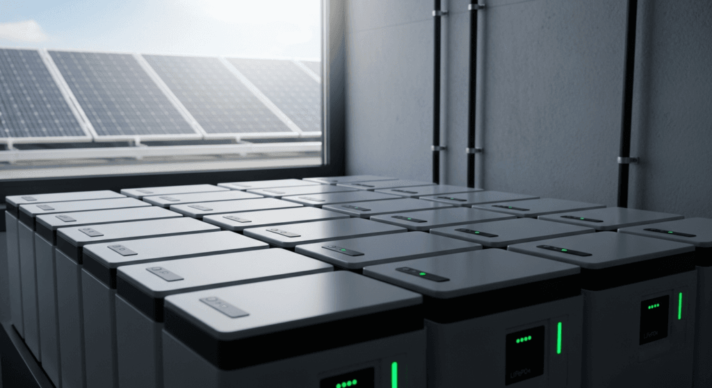
A home energy storage battery is no longer a luxury component for off-grid enthusiasts; it is the core technical pillar of the modern, resilient, and intelligent home. As we accelerate towards the 2026 energy landscape, the paradigm is shifting from passive energy consumption to active energy management. The grid is decentralizing, driven by the proliferation of distributed energy resources (DERs) and the rise of the “prosumer”—a homeowner who both produces and consumes energy. This transition is not just about backup power during an outage. It’s about a fundamental re-architecting of our relationship with energy, enabling grid-independence, optimizing time-of-use (TOU) rates, and providing grid services like frequency regulation. For engineers and technically-astute homeowners, understanding the physics, system synergies, and regulatory frameworks is not optional; it is an imperative for deploying a system that is safe, efficient, and delivers a quantifiable return on investment (ROI). At SolarKiit, our mission, as detailed on our About page, is to empower this transition with engineering-grade knowledge. This guide moves beyond the superficial marketing claims to provide a definitive technical reference, deconstructing the core principles you need to master to specify and operate a high-performance home energy storage battery.
The Core Physics and Chemistry of a Modern Home Energy Storage Battery
To truly master energy storage, one must first understand the fundamental science that governs it. The process is a beautiful dance of physics and chemistry, from the moment a photon strikes a solar panel to the instant an electron is dispatched to power a critical load. Generic explanations fail to capture the engineering elegance of the system. We must go deeper.
Photon Harvesting to Electron Storage: The Quantum Journey
It all begins with the photovoltaic (PV) effect. When photons from the sun, packets of light energy, strike a silicon atom in a solar cell, they can transfer their energy to an electron, liberating it from the atom and creating an “electron-hole pair.” An internal electric field, engineered into the cell’s p-n junction, forces these free electrons to flow in one direction, creating a direct current (DC). The efficiency of this photon conversion is a critical variable, benchmarked by institutions like the NREL Solar Efficiency Standards. This raw DC power is then managed by a charge controller before it reaches the battery. The goal is to harvest the maximum number of photons and convert them into a stable, usable flow of electrons destined for storage, a process that is the first step in any Best Off-Grid Solar Kits of 2024: The Ultimate Guide to Energy Independence.
The LiFePO4 Advantage: Deconstructing Intercalation
The dominant chemistry for residential applications today is Lithium Iron Phosphate (LiFePO4). The “why” is rooted in its molecular structure. Unlike the layered-oxide structures of NMC or LCO chemistries, LiFePO4 utilizes a robust, three-dimensional olivine crystal structure. During discharge, lithium ions (Li+) travel from the graphite anode, through the electrolyte, and insert themselves into the olivine lattice of the iron phosphate cathode—a process called intercalation. The reverse happens during charging. This process is remarkably stable for two key reasons:
- Strong Covalent Bonds: The P-O covalent bond within the (PO4)³⁻ polyanion is incredibly strong, keeping the oxygen atoms locked in the lattice even under abuse conditions like overcharging or physical damage. This structural integrity is what makes LiFePO4 batteries inherently resistant to thermal runaway and fire.
- Minimal Volumetric Change: The olivine structure undergoes very little change in volume during the intercalation and de-intercalation of lithium ions. This physical stability minimizes mechanical stress on the electrode materials, directly translating to a very high cycle life—often exceeding 6,000 cycles at 80% Depth of Discharge (DoD). This is the physics behind the longevity claims you see on spec sheets and a core topic in our Batteries Solaires LiFePO4 : Le Guide Ultime pour l’Énergie Renouvelable.
System Synergy: The Digital Handshake of BESS Components
A Battery Energy Storage System (BESS) is far more than a battery. It’s an ecosystem of intelligent components that must communicate flawlessly to optimize performance, ensure safety, and maximize lifespan. This digital “handshake” is where most of the engineering innovation is happening.
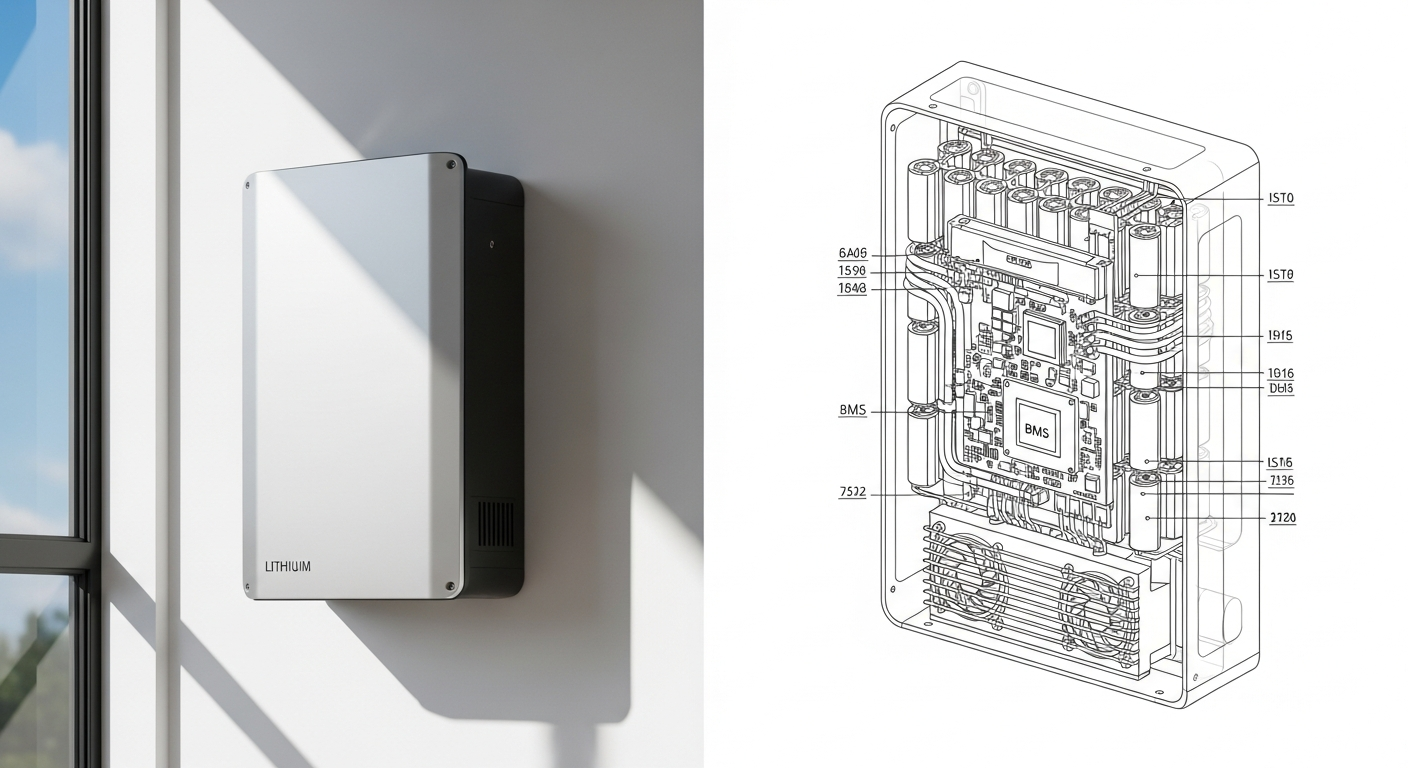
The Battery Management System (BMS): The System’s Central Nervous System
The BMS is the unsung hero of any advanced home energy storage battery. Its role is to be the central nervous system, monitoring and controlling every aspect of the battery’s state. A sophisticated BMS goes far beyond simple high/low voltage cutoffs. It performs critical functions like:
- Active Cell Balancing: While passive balancing bleeds excess charge from higher-voltage cells as heat, active balancing uses small converters to shuttle energy from the highest-charged cells to the lowest-charged cells. This dramatically improves usable capacity and efficiency, especially as the battery ages.
- State of Charge (SoC) & State of Health (SoH) Calculation: Using complex algorithms that incorporate voltage, current (coulomb counting), and temperature, the BMS provides an accurate real-time assessment of the battery’s condition, preventing damaging deep discharges and providing data for performance analysis.
- Thermal Management: It monitors cell temperatures and can control cooling fans or even throttle charge/discharge rates to keep the cells within their optimal operating window (typically 15°C to 35°C), which is paramount for both safety and longevity.
MPPT and Inverter: Calibrating the Flow of Energy
The handshake between the solar array, battery, and home loads is managed by the Maximum Power Point Tracker (MPPT) charge controller and the inverter. The MPPT’s job is to continuously adjust the electrical operating point (voltage and current) of the solar array to extract the maximum possible power as irradiance and temperature fluctuate. It’s a dynamic optimization algorithm running in real-time. The inverter then converts the DC power from the PV array or battery into the AC power required by your home. The quality of a modern inverter is defined by its efficiency and its waveform. A pure sine wave inverter, as opposed to a modified sine wave, is essential for the safe and efficient operation of sensitive electronics, motors, and medical equipment. To dive deeper, consult our guide on Solar Inverter Efficiency: The Ultimate Guide to Maximizing Your PV System’s Output & ROI.
Sizing Your Home Energy Storage Battery: An Engineer’s Formula
Properly sizing a battery system is a critical engineering task that balances cost, performance, and desired autonomy. A common mistake is to focus solely on total kWh capacity. A professional analysis, like what we provide when you Contact our engineering team, focuses on the load profile. The core formula is a starting point:
Battery Capacity (kWh) = (Daily Energy Consumption (kWh) × Days of Autonomy) / (Depth of Discharge (DoD) × System Efficiency)
Deconstructing the Variables: Load Profiles and Surge Capacity
The variables in this formula require careful consideration.
- Load Profile: This is more important than your total daily kWh. You must differentiate between your baseload (refrigerators, servers, networking gear) and your peak loads (HVAC, electric vehicle chargers, well pumps). A system must be sized to handle the continuous baseload for the desired autonomy period, while the inverter must have the surge capacity to handle the high inrush current of inductive loads (motors) starting up.
- Days of Autonomy: This is the number of consecutive days with zero solar input (e.g., due to storms) that your system can sustain your critical loads. For grid-tied backup, 1-2 days is common. For a fully off-grid home, 3-5 days is a safer benchmark.
- Depth of Discharge (DoD): For LiFePO4, a DoD of 80-90% is standard practice to maximize usable capacity without significantly impacting cycle life. Discharging to 100% is possible but will accelerate degradation.
- System Efficiency: This accounts for energy losses in the inverter (DC to AC conversion) and the battery itself (charging/discharging). This is also known as round-trip efficiency, which for a quality LiFePO4 system is typically 90-95%.
This detailed approach is essential for any serious DIY Solar Panel Installation: The Ultimate Guide for Homeowners in 2026.
2026 Market Benchmark: A Comparative Analysis of Leading BESS Models
To provide a clear engineering benchmark, we’ve compiled data on five leading battery systems expected to dominate the 2026 market. Note that Levelized Cost of Storage (LCOE) is a calculated metric representing the total lifetime cost per kWh discharged, a critical metric for ROI analysis.
| Model | Usable Capacity (kWh) | Chemistry | Cycles @ 80% DoD | Warranty | Est. LCOE ($/kWh) |
|---|---|---|---|---|---|
| SolarKiit PowerCore 15 | 15.2 | LiFePO4 | 8,000 | 15 Years / 8,000 Cycles | $0.12 |
| Tesla Powerwall 3 | 13.5 | NMC | 4,000 | 10 Years / Unlimited Cycles | $0.18 |
| Enphase IQ Battery 5P | 5.0 (Modular) | LiFePO4 | 6,000 | 15 Years / 6,000 Cycles | $0.15 |
| FranklinWH aPower | 13.6 | LiFePO4 | 4,500 | 12 Years / 43 MWh Throughput | $0.17 |
| SunPower SunVault | 13.0 (Expandable) | LiFePO4 | 4,000 | 10 Years / 70% Capacity | $0.20 |
Navigating the Regulatory Maze: UL 9540 and NEC 2026
Deploying a home energy storage battery safely and legally requires navigating a complex web of codes and standards. These are not suggestions; they are mandatory requirements to ensure the safety of your property and first responders. A failure to comply can result in failed inspections, denied insurance claims, and catastrophic safety failures.
UL 9540 & UL 9540A: The Gold Standard for Safety
The most critical standard to understand is UL 9540, “The Standard for Energy Storage Systems and Equipment.” This certification is not for the battery alone but for the entire pre-packaged system: the battery, inverter, BMS, and enclosure. It ensures all components work together safely. A key component of this is UL 9540A, which is a test method, not a certification. It evaluates the risk of thermal runaway fire propagation. A system that has passed UL 9540A testing at the cell, module, and unit level has demonstrated that if a single cell fails, the fire will not cascade to adjacent cells or units. This is the highest level of safety validation available and a non-negotiable requirement for any system installed inside a home or attached garage. Always verify the certification with trusted sources like UL Solutions (Solar Safety).
Decoding NEC 2026 for Energy Storage Systems
The NFPA 70: National Electrical Code (NEC) provides the installation requirements. Article 706, “Energy Storage Systems,” is the primary reference. Key provisions that will be enforced in 2026 include:
- Location: Strict rules on installation in habitable spaces and requirements for physical separation or fire-rated barriers. For example, NEC 706.11 specifies spacing requirements between units to prevent fire propagation.
- Rapid Shutdown: Systems must have a means to rapidly shut down the PV array and the battery system at the initiation of an emergency responder, de-energizing conductors to a safe level.
- Signage: Clear and specific labeling is required at the service disconnect and on the ESS unit itself to alert first responders to the presence of an energy storage system.
Understanding these codes is a core part of specifying a compliant battery storage system for home.
Advanced Engineering FAQ: Optimizing Your Home Energy Storage Battery
How does ambient temperature *really* affect LiFePO4 battery lifespan and performance?
Temperature is the single most significant factor in battery degradation, both for performance and calendar life. While LiFePO4 is more thermally stable than NMC, its performance is still highly dependent on temperature. The ideal operating range is 15°C to 35°C (60°F to 95°F).
- High Temperatures (>35°C): Heat accelerates the parasitic chemical reactions within the cell, primarily the growth of the Solid Electrolyte Interphase (SEI) layer on the anode. This consumes lithium ions and increases internal resistance, permanently reducing capacity. A quality BMS will actively cool the cells or throttle performance to mitigate this.
- Low Temperatures (<5°C): Charging a lithium-ion battery below freezing is extremely dangerous. The rate of lithium ion intercalation into the graphite anode slows dramatically. Instead, lithium can “plate” on the surface of the anode as metallic lithium. This not only reduces capacity but can form dendrites that may pierce the separator, causing an internal short circuit and catastrophic failure. A sophisticated BMS will prevent charging below a set temperature (e.g., 0-5°C) or use internal heaters. This is a key differentiator in systems designed for cold climates, such as our portable solar generators.
What is the engineering trade-off between a DC-coupled and an AC-coupled system?
The choice between AC and DC coupling is a fundamental architectural decision with direct impacts on efficiency and flexibility. There is no single “best” answer; it depends on the specific application.
- DC-Coupled: Solar panels generate DC, and batteries store DC. In a DC-coupled system, the solar energy flows through a charge controller directly to the battery. The battery power is only inverted to AC when it’s needed by the home. This is more efficient for new installations that prioritize self-consumption of solar energy, as it avoids the “conversion penalty” of going from DC (solar) to AC (grid) and back to DC (battery).
- AC-Coupled: In an AC-coupled system, the solar panels have their own grid-tied inverter (or microinverters) that converts DC to AC at the source. To charge the battery, a separate battery inverter converts this AC power back to DC. This is less efficient due to the extra conversion step (DC -> AC -> DC). However, it is far easier and more cost-effective for retrofitting a battery system onto an existing solar installation. It also allows for more flexible placement of the battery, as it doesn’t need to be near the solar charge controller.
Can I oversize my PV array relative to my battery and inverter capacity, and what are the technical implications?
Yes, oversizing the PV array (increasing the DC-to-AC ratio) is a standard engineering practice to maximize energy harvest, but it must be managed by the system’s electronics. A common ratio is 1.2 to 1.5 (e.g., 12 kW of solar panels on a 10 kW inverter). The primary benefit is increased energy production during non-peak hours (early morning, late afternoon, and overcast days), helping to fully charge the battery more consistently.
- Inverter Clipping: During peak sun hours (midday on a clear day), the PV array may produce more DC power than the inverter can convert to AC. The inverter will “clip” this excess power, limiting its output to its maximum rating. While this seems wasteful, the energy gained during the shoulders of the day often outweighs the small amount of clipped energy at noon.
– BMS & Charge Controller Role: The MPPT charge controller and BMS are critical here. They must be rated to handle the maximum voltage (Voc) and current (Isc) of the oversized array, especially in cold weather when voltage increases. The system will intelligently throttle the PV output once the battery reaches 100% SoC to prevent overcharging.
Beyond cycle life, what is calendar aging and how do I mitigate it?
Calendar aging is the irreversible capacity loss that occurs over time, regardless of whether the battery is being used, and it can be a more significant factor than cycle aging in some applications. It is primarily driven by temperature and state of charge (SoC).
- The Mechanism: The primary driver is the slow, continuous growth of the SEI layer on the anode, which consumes lithium from the electrolyte and increases internal resistance. This reaction is always occurring, but its rate is highly dependent on environmental conditions.
- Mitigation Strategies:
- Thermal Management: Storing the battery in a cool, climate-controlled environment (ideally around 20-25°C) is the most effective strategy. Avoid hot attics or uninsulated garages in warm climates.
- SoC Management: Lithium-ion batteries are most “stressed” when held at very high or very low states of charge. For long-term storage (e.g., a seasonal cabin), it’s best to leave the battery at an SoC of 40-60%. A modern BMS will have a “storage mode” or allow you to set a maximum SoC limit (e.g., 80%) for daily use to reduce time spent at 100%, thereby slowing calendar aging.
This is a key consideration we explain in our Privacy Policy when discussing data used for system optimization.
What is “voltage sag” under heavy load, and how does a quality BMS and inverter architecture minimize it?
Voltage sag is the temporary drop in a battery’s terminal voltage when a large electrical load is applied, and minimizing it is a key indicator of a high-performance system. All batteries have internal resistance. According to Ohm’s Law (V = IR), when the current (I) drawn by a load increases, the voltage drop (V_drop) across that internal resistance (R) also increases. This causes the terminal voltage available to the inverter to “sag.”
- The Problem: If the voltage sags too much, it can fall below the inverter’s low-voltage cutoff threshold, causing the inverter to shut down prematurely even if the battery still has significant energy stored. This is common when starting large motors (like an air conditioner or well pump) which have a high inrush current.
- The Solution: A superior architecture minimizes sag through several means:
- Low Internal Resistance Cells: High-quality LiFePO4 cells are engineered for low internal resistance.
- Powerful Inverter: A robust inverter has large capacitors that can supply the initial surge of current, reducing the instantaneous demand on the battery itself.
- Intelligent BMS: The BMS communicates with the inverter, anticipating the load and managing the power delivery to prevent the voltage from crashing below the critical threshold. This is the mark of a truly integrated home energy storage battery.
The journey to true energy autonomy is an engineering challenge. It requires moving beyond simple specifications and understanding the fundamental principles that govern a system’s performance, safety, and longevity. By focusing on quality chemistry, intelligent system synergy, and strict adherence to regulatory standards, you can deploy a solution that provides not just backup power, but a cornerstone for the future of residential energy. The key is a well-engineered and properly specified home energy storage battery.
📥 Associated Resource:

El Kouriani Abde Civil Engineer & Founder of SolarKiit
El Kouriani Abde is a seasoned Civil Engineer and Project Manager with over 21 years of field experience. As the founder and publisher of SolarKiit.com, he leverages his deep technical background to simplify complex renewable energy concepts. His mission is to provide homeowners and professionals with accurate, engineering-grade guides to maximize their solar investments and achieve energy independence.