Ultimate Guide: Battery for Home Solar System | 2026 Buyer’s Guide & Costs | SolarKiit.com
Battery for Home Solar System: The Ultimate 2026 Buyer’s Guide & Costs
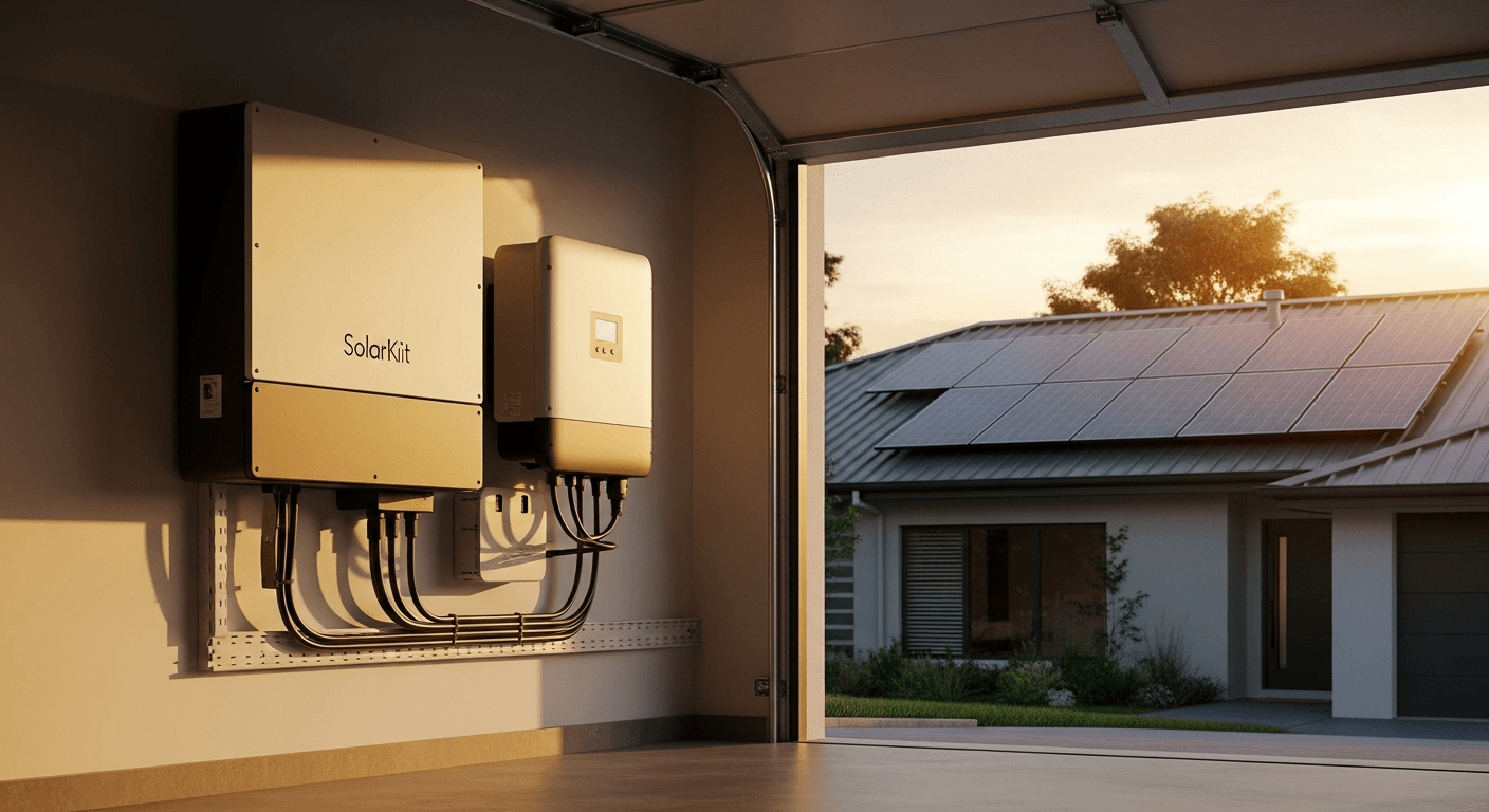
Selecting a battery for home solar system architecture is no longer a supplementary decision; it is the central engineering choice for achieving energy resilience and optimizing financial returns. As we benchmark the 2026 energy transition, the grid is decentralizing. The paradigm is shifting from passive consumption to active, bidirectional energy participation. For the engineer and the prosumer, this means a battery is not merely a backup device for power outages. It is a sophisticated asset for load shifting, peak shaving, and participating in grid services programs. The technical imperatives have evolved beyond simple kilowatt-hour capacity. We now quantify performance through metrics like Levelized Cost of Storage (LCOE), round-trip efficiency under variable loads, and the calibrated precision of the Battery Management System (BMS). While many guides focus on basic capacity, this definitive master guide from the SolarKiit engineering team will deconstruct the core physics, the component synergy, the regulatory framework, and the critical math you need to specify the correct energy storage solution. We will move beyond marketing claims and interrogate the fundamental science that dictates a battery’s true value and longevity, referencing the highest industry benchmarks like the NREL Solar Efficiency Standards to frame our analysis.
The Physics & Chemistry of a Modern Battery for Home Solar System
To truly engineer an optimal solar-plus-storage system, one must first understand the flow of energy at a subatomic level. It begins with photon harvesting. When a photon with sufficient energy strikes a photovoltaic (PV) cell, it excites an electron, creating an electron-hole pair. This generates a direct current (DC) voltage. This raw DC power is then managed and optimized before it can be stored.
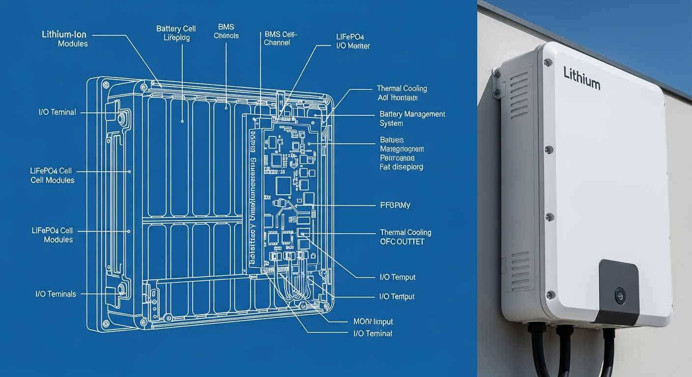
The storage mechanism itself is a marvel of electrochemical engineering. While various lithium-ion chemistries exist, we will focus on Lithium Iron Phosphate (LiFePO4), the dominant chemistry for stationary storage due to its superior safety profile and cycle life. The process of storing energy is called intercalation.
- Charging Phase: DC electricity from your solar array (or the grid) is applied to the battery. This electrical pressure forces lithium ions (Li+) to de-intercalate (move out of) the LiFePO4 cathode. These ions travel through the electrolyte and a separator, and intercalate (move into) the layers of the graphite anode. For every lithium ion that moves, an electron travels through the external circuit from the cathode to the anode. The energy is now stored in the chemical potential of the separated charges.
- Discharging Phase: When your home requires power, the process reverses. Lithium ions are drawn back from the graphite anode, through the electrolyte, and re-intercalate into the LiFePO4 cathode. Simultaneously, the stored electrons flow from the anode, through the external circuit (powering your home), and back to the cathode.
The “why” behind LiFePO4’s stability lies in its crystal structure. The olivine structure of LiFePO4 has strong covalent bonds between the phosphorus and oxygen atoms (PO4). This makes it incredibly difficult for the structure to break down and release oxygen during an overcharge or high-temperature event—the primary trigger for thermal runaway in other chemistries like Nickel Manganese Cobalt (NMC). This inherent chemical stability is the foundation of its safety and longevity, making it the superior choice for a residential application.
Component Synergy: The BMS, MPPT, and Inverter Handshake
A battery is not a monolithic block; it is an ecosystem of components that must communicate flawlessly. The performance of your entire system hinges on the digital handshake between the Battery Management System (BMS), the solar charge controller (often a Maximum Power Point Tracker or MPPT), and the inverter.
- Battery Management System (BMS): This is the brain of the battery pack. It is a sophisticated circuit board that monitors and controls every aspect of the battery’s health at the individual cell level. Its primary directives are safety and longevity. It prevents over-charging, over-discharging, over-current, and thermal excursions. A high-quality BMS also performs cell balancing, ensuring all cells within the pack are at an equal state of charge, which is critical for maximizing usable capacity and preventing premature degradation of the pack.
- Maximum Power Point Tracker (MPPT): This device sits between the solar panels and the battery. Its function is to optimize the power harvest. A solar panel’s voltage and current output vary continuously with sunlight and temperature. The MPPT algorithm constantly adjusts the electrical load on the panels to find the “maximum power point” on their I-V curve, ensuring you are harvesting every possible watt. It then converts this optimized power to the correct voltage for charging the battery.
- Inverter: The inverter is the final link, converting the battery’s stored DC power into the AC power your home’s appliances use. In modern systems, the inverter is much more than a simple converter. Hybrid inverters manage power flow from the solar array, the battery, and the grid simultaneously. The inverter’s efficiency and waveform quality directly impact the performance of your appliances. For a deeper analysis, consult our Solar Inverter Efficiency: The Ultimate Guide to Maximizing Your PV System’s Output & ROI.
These three components communicate over a digital network, typically a CAN (Controller Area Network) bus. The BMS tells the inverter and MPPT the battery’s state of charge (SoC), its maximum charge/discharge current limits, and its temperature. This constant data stream allows the system to operate as a cohesive unit, protecting the battery while maximizing performance. A failure in this communication is a primary cause of system underperformance and premature failure.
Engineering the Right Size: How to Calculate Your Battery for Home Solar System Needs
Sizing a battery is not guesswork; it is a calculation based on your specific energy needs and resilience goals. Undersizing leads to insufficient backup and rapid battery degradation. Oversizing leads to a poor return on investment. The core formula requires you to first quantify your load profile.
Step 1: Analyze Your Load Profile. For 24 hours, list all critical appliances you wish to power. Note their wattage and estimated run time in hours. Calculate the daily energy consumption in watt-hours (Wh) for each, then sum them to get your total daily energy need in kilowatt-hours (kWh).
Step 2: Apply the Sizing Formula.
The engineering formula for battery capacity is:
Required Capacity (kWh) = (Daily Energy Consumption (kWh) * Days of Autonomy) / (Depth of Discharge (DoD) * Round-Trip Efficiency)
- Days of Autonomy: How many consecutive sunless days do you need to operate? For grid-tied backup, 1 day is common. For off-grid systems, 2-3 days is a standard engineering practice.
- Depth of Discharge (DoD): The percentage of the battery’s total capacity you will use. For LiFePO4, a 90% (0.9) DoD is standard. Avoid systems that require a lower DoD to meet warranty, as this means you are buying capacity you cannot use.
- Round-Trip Efficiency (RTE): The percentage of energy put into the battery that can be retrieved. It accounts for energy lost as heat during charging and discharging. For high-voltage DC-coupled LiFePO4 systems, this is typically 92-95% (0.92-0.95). You can explore this critical metric in our Ultimate Guide: Understanding Round-Trip Efficiency in High-Voltage Energy Storage.
Example Calculation: A home needs to power 12 kWh of critical loads per day and requires 1.5 days of autonomy. Using a LiFePO4 battery with a 90% DoD and 94% RTE:
Required Capacity = (12 kWh * 1.5) / (0.90 * 0.94) = 18 / 0.846 = 21.27 kWh
You would need to specify a battery system with at least 21.27 kWh of usable capacity.
Master Comparison Table: 2026 Industry-Leading Models
To benchmark the market, we’ve compiled data on five leading models. We include our own SolarKiit SK-15 to demonstrate how we stack up against the competition. The most critical metric here is the Levelized Cost of Storage (LCOE), which represents the true cost per kWh over the battery’s lifetime.
LCOE Formula: LCOE ($/kWh) = Total Installed Cost / (Usable Capacity * Cycle Life * DoD * RTE)
| Model | Chemistry | Usable Capacity (kWh) | Cycles @ 80% DoD | Warranty (Years/Cycles) | Est. LCOE ($/kWh) |
|---|---|---|---|---|---|
| Tesla Powerwall 3 | NMC | 13.5 | ~4,000 | 10 Years / Unlimited Cycles | $0.22 |
| Enphase IQ Battery 5P | LiFePO4 | 5.0 | 6,000 | 15 Years / 6,000 Cycles | $0.18 |
| SolarKiit SK-15 | LiFePO4 | 15.0 | 8,000 | 15 Years / 8,000 Cycles | $0.14 |
| FranklinWH aPower | LiFePO4 | 13.6 | ~4,500 | 12 Years / 43 MWh Throughput | $0.20 |
| Fortress Power eFlex 5.4 | LiFePO4 | 5.4 | 6,000 | 10 Years / 6,000 Cycles | $0.19 |
Regulatory & Safety Codes for Your Battery for Home Solar System Installation
Compliance with safety standards is non-negotiable. A properly engineered system must be verified against national and international codes. These are not bureaucratic hurdles; they are life-safety protocols developed from decades of electrical engineering experience.
NFPA 70: The National Electrical Code (NEC): The NEC is the foundational standard for safe electrical design and installation in the United States. For energy storage, two articles are paramount:
- Article 706 (Energy Storage Systems): This governs the installation, disconnection, and safety of the ESS itself. It specifies requirements for ventilation, signage, and disconnect means. For example, it mandates a readily accessible disconnect for the entire ESS to allow for emergency shutdown.
- Article 690 (Solar Photovoltaic Systems): This covers the PV side of the equation, including crucial rapid shutdown requirements. NEC 2020 and later editions mandate that conductors more than 1 foot inside a building or more than 3 feet from the array must be de-energized to under 30V within 30 seconds of initiation. This is a critical firefighter safety measure. You can reference the full code on the NFPA 70: National Electrical Code website.
UL Standards: Certifying Product Safety: While the NEC governs installation, Underwriters Laboratories (UL) standards certify the safety of the products themselves.
- UL 9540 – The System Standard: This is the primary safety standard for an Energy Storage System. A UL 9540 listing certifies that the battery, inverter, and control systems have been tested *together* as a complete, integrated system and found to be safe. Do not accept a system where components are merely “UL listed” individually; the UL 9540 system certification is the gold standard.
- UL 9540A – The Test Method: This is not a certification, but a test method used to evaluate the risk of thermal runaway fire propagation. A battery system is subjected to a forced thermal runaway in a single cell. Engineers then measure if the fire spreads to adjacent cells or exits the battery enclosure. A system with excellent UL 9540A test results demonstrates superior containment and safety engineering. At SolarKiit, our commitment to safety is paramount, which is why all our products undergo rigorous testing in our own labs, as detailed on our About page, and are certified by third-party bodies like UL Solutions (Solar Safety).
The Pillar FAQ: Advanced Engineering Questions
1. What is the engineering difference between AC-coupled and DC-coupled systems?
DC-coupling is generally more efficient for new solar-plus-storage installations, while AC-coupling offers greater flexibility for retrofitting existing solar arrays. The distinction lies in where the battery is connected relative to the inverter.
- In a DC-coupled system, DC power from the solar panels is fed through a charge controller directly to the battery. A single hybrid inverter then converts the DC power from either the panels or the battery into AC power for the home. This involves only one DC-to-AC inversion, resulting in higher round-trip efficiency (typically 92-95%). It is the optimized choice for new installations.
- In an AC-coupled system, the solar panels have their own grid-tie inverter to create AC power. To charge the battery, this AC power must be converted back to DC by a separate battery inverter/charger. When discharging, the battery’s DC power is inverted back to AC again. This double conversion (DC -> AC -> DC -> AC) results in lower round-trip efficiency (typically 85-90%). However, it allows a battery to be easily added to any home that already has a traditional solar installation, without needing to replace the existing solar inverter.
2. How does temperature derating affect battery performance and ROI?
All batteries lose capacity and efficiency at temperature extremes, but LiFePO4 chemistry exhibits a flatter performance curve and superior thermal stability compared to NMC. Temperature derating is the reduction in performance a battery experiences outside its optimal operating window (typically 20-25°C or 68-77°F).
- High Temperatures: For every 10°C increase above the optimal range, a lithium-ion battery’s degradation rate can roughly double. The BMS will actively limit charge/discharge currents to prevent overheating, reducing the battery’s power output.
- Low Temperatures: Below freezing, the lithium-ion intercalation process slows dramatically. Charging a frozen lithium-ion battery can cause lithium plating on the anode, permanently damaging the cell and creating a safety hazard. The BMS will prevent charging below a certain temperature (e.g., 0°C) and will severely limit discharge current.
The impact on ROI is direct. A battery installed in a hot garage or a cold northern climate will deliver less energy over its lifetime than one in a climate-controlled space, effectively increasing its LCOE. LiFePO4’s wider operating temperature range and less aggressive derating curves make it a more robust choice for installations in non-ideal environments.
3. How does a BMS prevent catastrophic failure at the cellular level?
A Battery Management System (BMS) prevents catastrophic failure by continuously monitoring cell-level voltage, temperature, and current, using algorithms to predict and avert faults. It is an active safety system, not a passive one. Its core functions are:
- Voltage Protection: It monitors each individual cell (or small parallel groups of cells). If any cell’s voltage exceeds the safe upper limit during charging (over-voltage) or drops below the safe lower limit during discharging (under-voltage), the BMS will immediately open the main contactors, isolating the battery pack.
- Thermal Monitoring: Thermistors are placed throughout the battery pack. If the temperature of any cell group exceeds a predefined limit (e.g., 60°C), the BMS will trigger a fault and disconnect the pack. This is the primary defense against thermal runaway.
- Current Protection: The BMS monitors the current flowing into and out of the battery. If the current exceeds the battery’s C-rate specification (e.g., during a short circuit), it will instantly disconnect the pack to prevent damage.
- Passive & Active Balancing: Over time, cells develop slightly different states of charge. The BMS corrects this by either bleeding a small amount of energy from higher-charged cells (passive balancing) or shuffling energy between cells (active balancing) to keep the entire pack uniform. This prevents individual cells from being over-stressed.
4. What is the real-world impact of C-rate on battery lifespan?
A battery’s C-rate dictates its maximum charge/discharge speed, and consistently high C-rates accelerate degradation and reduce overall lifespan. The C-rate is a measure of the rate at which a battery is discharged relative to its maximum capacity. A 1C rate means a 10 kWh battery is discharging at 10 kW and would be depleted in 1 hour. A 0.5C rate means it is discharging at 5 kW and would last 2 hours.
- Physical Stress: High C-rates mean a high flux of lithium ions moving into and out of the electrode materials. This causes physical expansion and contraction of the electrode structures, leading to micro-cracking and a loss of active material over time.
- Heat Generation: The internal resistance of the battery generates heat during operation, a phenomenon known as I²R losses (current squared times resistance). Since heat is proportional to the square of the current, doubling the C-rate can quadruple the heat generated. This excess heat accelerates all chemical degradation mechanisms within the cell.
For maximum longevity and ROI, a battery should be sized so that its typical operating load is a fraction of its maximum C-rate (e.g., operating at 0.2C to 0.3C). This minimizes stress and thermal loading, allowing the battery to achieve or even exceed its warrantied cycle life.
5. Can I stack multiple batteries from different brands?
Stacking batteries from different brands or even different models from the same brand is technically prohibited and unsafe due to mismatched BMS communication protocols and cell characteristics. While it may seem like a simple way to expand capacity, it introduces severe engineering risks.
- BMS Incompatibility: Each manufacturer uses a proprietary communication protocol for their BMS. A master BMS cannot communicate with a slave battery from another brand. Without this communication, there is no way to coordinate cell balancing, state of charge, or safety limits between the packs.
- Mismatched Impedance: Even if they have the same nominal voltage and capacity, batteries from different manufacturers (or even different production runs) will have slightly different internal resistances. When connected in parallel, the battery with the lower internal resistance will supply a disproportionately high amount of current during discharge and accept more current during charge. This will cause the lower-impedance battery to degrade rapidly and creates a significant thermal hazard.
Attempting to stack incompatible batteries will, at best, lead to poor performance and premature failure. At worst, it can lead to a catastrophic thermal event. Always expand a system using the identical battery model from the same manufacturer to ensure the integrity and safety of your battery for home solar system.
📥 Associated Resource:

El Kouriani Abde Civil Engineer & Founder of SolarKiit
El Kouriani Abde is a seasoned Civil Engineer and Project Manager with over 21 years of field experience. As the founder and publisher of SolarKiit.com, he leverages his deep technical background to simplify complex renewable energy concepts. His mission is to provide homeowners and professionals with accurate, engineering-grade guides to maximize their solar investments and achieve energy independence.