battery power station: The Ultimate Guide to Reliable & Portable Power Solutions
The energy landscape of 2026 is defined by decentralization and resilience. As grid infrastructure faces increasing strain from climate events and fluctuating demand, consumers and professionals are architecting personal energy ecosystems. The battery power station has evolved from a simple camping accessory into the command center of this new paradigm, serving as the critical link between intermittent renewable generation and consistent, reliable power delivery.
This shift is driven by advancements in battery chemistry, inverter technology, and intelligent energy management. No longer are we just concerned with keeping phones charged; we are now powering entire home offices, critical medical equipment, and professional toolsets off-grid. The market is demanding not just capacity, but efficiency, safety, and seamless integration with solar assets.
In this guide, we move beyond marketing claims to deliver an engineering-level analysis of the technologies that define a modern battery power station. We will dissect the components, from the photovoltaic cell to the AC outlet, providing the technical foundation needed to design and deploy a robust, portable power solution that meets the rigorous demands of 2026 and beyond.
Deep Technical Analysis: From Photon to Appliance
Understanding a battery power station requires a granular analysis of its core subsystems: the energy generation source (solar panels), the charge controller, the energy storage medium (battery), and the power delivery system (inverter). The overall system efficiency is a product of the efficiencies of these individual components.
The Physics of Energy Conversion and Storage
The process begins with the photovoltaic (PV) effect. When photons from sunlight strike a solar panel’s semiconductor material (typically monocrystalline silicon), they excite electrons, creating a direct current (DC) flow. The voltage and current produced by a panel are variable, dependent on solar irradiance (W/m²) and cell temperature. This raw, unregulated DC power is unsuitable for direct battery charging.
This is where the Maximum Power Point Tracking (MPPT) charge controller becomes critical. An MPPT is a high-frequency DC-to-DC converter. It continuously samples the PV array’s voltage and current to calculate the operating point (the “knee” of the I-V curve) that yields maximum power output. It then adjusts its internal conversion to “pull” this optimal power from the panel and transform it to the correct voltage required by the battery, achieving efficiencies exceeding 99% in modern units.
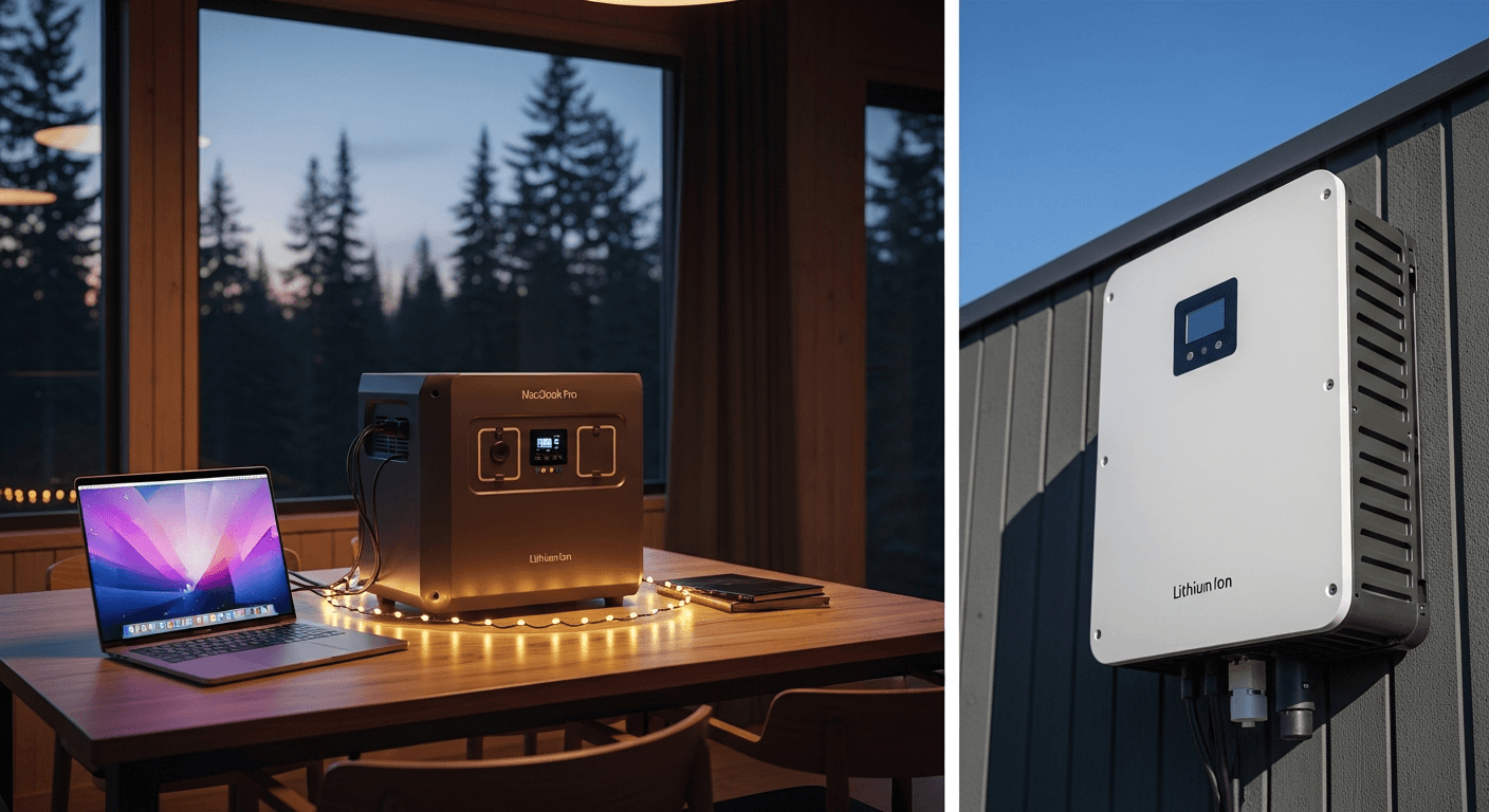
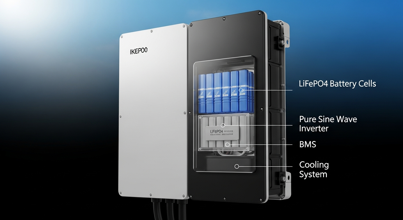
The conditioned DC energy is then stored electrochemically. By 2026, the dominant chemistry for this application is Lithium Iron Phosphate (LiFePO4). During charging, lithium ions are extracted from the iron phosphate cathode and intercalate into the graphite anode. This process is reversed during discharge. The inherent stability of the phosphate-oxide bond makes LiFePO4 far less prone to thermal runaway than older chemistries like Lithium Nickel Manganese Cobalt (NMC), a paramount safety feature.
Finally, to power common household appliances, the stored DC energy must be converted to Alternating Current (AC). This is the job of the inverter. A Pure Sine Wave inverter uses sophisticated pulse-width modulation (PWM) to generate a smooth, clean AC waveform that precisely mimics grid power. This is non-negotiable for sensitive electronics, variable-speed motors, and medical devices, which can be damaged by the “choppy” output of a modified sine wave inverter.
Efficiency Benchmarks and System Losses
A system’s “photon-to-appliance” efficiency is a cascade of individual component efficiencies. By 2026, benchmark figures are:
- PV Panel Efficiency: Monocrystalline TOPCon (Tunnel Oxide Passivated Contact) or HJT (Heterojunction) cells will achieve 23-25% conversion efficiency under Standard Test Conditions (STC).
- MPPT Controller Efficiency: Leading units from Victron or EPEVER operate at 98-99.5% efficiency, minimizing solar harvesting losses.
- Battery Round-Trip Efficiency: LiFePO4 batteries boast a round-trip efficiency of 92-95%. This means for every 100Wh of energy put in, 92-95Wh can be retrieved.
- Inverter Efficiency: High-frequency Pure Sine Wave inverters achieve 95-98% efficiency at their optimal load. Efficiency drops at very low or very high loads.
Consider a system with a 24% efficient panel, 99% MPPT, 95% battery, and 96% inverter. The total system efficiency is approximately 0.24 × 0.99 × 0.95 × 0.96 = 0.216, or 21.6%. This calculation highlights how every component’s performance is critical to maximizing the utility of the initial solar energy captured.
Load Calculation and Sizing Strategy
Properly sizing a power station is the most critical step. This involves a two-part calculation: energy capacity (in Watt-hours) and power output (in Watts).
1. Energy Capacity (Watt-hours, Wh): This determines how long you can run your devices. First, list all appliances you intend to power. For each, find its power consumption in Watts and estimate the daily hours of use.
Formula: Daily Energy Need (Wh) = Σ (Appliance Watts × Hours of Use)
For example: a 60W refrigerator running for 8 hours/day (33% duty cycle), a 15W laptop for 5 hours, and two 10W LED lights for 4 hours.
Daily Need = (60W × 8h) + (15W × 5h) + (2 × 10W × 4h) = 480Wh + 75Wh + 80Wh = 635Wh.
To account for inverter inefficiency and provide a buffer, a safety margin of 20-25% is recommended.
Required Capacity = 635Wh × 1.25 = ~794Wh. A 1000Wh (1kWh) power station would be a suitable choice.
2. Power Output (Watts, W): This determines which devices you can run simultaneously. The inverter must supply both the continuous load and the surge (or inrush) current required by motor-driven appliances like refrigerators or power tools.
Continuous Load: Sum the wattage of all devices running at the same time. In our example, if all run together: 60W + 15W + 20W = 95W.
Surge Load: The refrigerator’s compressor might require 3-5 times its running wattage to start. A 60W fridge could have a surge of 300W. The inverter must have a peak/surge rating that exceeds the single highest surge device. A 1500W continuous / 3000W surge inverter would be more than adequate.
Engineering Specifications & Innovations in 2026
The competitive landscape is driving rapid innovation, with brands differentiating through proprietary technologies and advanced system integration. The trend is toward modular, scalable ecosystems that blur the line between portable power and whole-home backup.
EcoFlow’s DELTA Pro Ecosystem: EcoFlow continues to lead in high-power, expandable systems. Their DELTA Pro series, with its 3.6kWh base unit expandable to 25kWh, exemplifies this modularity. A key 2026 innovation is their refined X-Boost technology, an adaptive voltage control algorithm within the inverter. It allows the unit to power devices with a rated wattage higher than the inverter’s continuous output by slightly lowering the voltage, a crucial feature for handling demanding tools on a job site without tripping the system.
Bluetti’s AC500 & Sodium-Ion Advancements: Bluetti’s flagship AC500 is a purely modular system; the control unit contains no internal battery. It pairs with B300S (LiFePO4) or other battery modules, allowing for unparalleled customization. By 2026, Bluetti is expected to be among the first to commercialize Sodium-Ion (Na-ion) battery packs. While offering slightly lower energy density than LiFePO4, Na-ion cells promise superior cold-weather performance, enhanced safety, and are built from abundant, inexpensive materials, potentially lowering system costs significantly.
Victron Energy’s Component-Based Dominance: For professional and off-grid applications, Victron remains the engineering standard. Rather than an all-in-one box, a Victron system is built from discrete, best-in-class components: a MultiPlus-II inverter/charger, a SmartSolar MPPT, and SmartShunt for battery monitoring, all communicating via the VE.Bus protocol. This allows for extreme customization and serviceability. Their 2026 offerings feature enhanced grid-forming capabilities, allowing a MultiPlus unit to create a stable microgrid during an outage with seamless solar integration.
Perovskite-on-Silicon PV Integration: A major advancement on the generation side is the integration of tandem solar cell technology. Portable panels utilizing a thin, highly efficient Perovskite layer atop a traditional silicon cell are entering the market. This combination captures a broader spectrum of light, pushing practical panel efficiencies toward 30%. This means faster charging times from a smaller, more portable solar array, a game-changer for mobile applications.
Technical Comparison of 2026 Leading Models
| Model / Kit | Battery Capacity (Wh) | Inverter Output (W Continuous / Surge) | Max Solar Input (W) | Key Engineering Feature |
|---|---|---|---|---|
| EcoFlow DELTA Pro 2 | 4,000 Wh (LiFePO4), expandable to 28 kWh | 4,000 W / 7,200 W | 2,000 W (Dual MPPT) | X-Boost 2.0 adaptive voltage control; 800V architecture for faster charging. |
| Bluetti AC600 + B400S | 4,096 Wh (LiFePO4), expandable to 32 kWh | 6,000 W / 10,000 W | 3,000 W (Expandable to 8,000 W) | Fully modular control/battery units; optional Sodium-Ion battery compatibility. |
| Victron Pro-Kit 3kVA | 5,120 Wh (LiFePO4 Smart Battery) | 2,400 W / 5,500 W | 1,450 W (SmartSolar MPPT 250/100) | Component-based system with VE.Bus communication for advanced control and grid-forming. |
| Anker SOLIX F3800 | 3,840 Wh (LiFePO4), expandable to 26.9 kWh | 6,000 W / 9,000 W (240V Split-Phase) | 2,400 W | Integrated 240V output for direct connection to home panels; GaN inverter tech. |
| SolarKiit SK-4000X | 4,200 Wh (Solid-State Li-Metal), expandable | 4,500 W / 8,000 W | 2,200 W (Perovskite-optimized MPPT) | Hypothetical 2026 model with solid-state battery for 30% higher energy density and 5,000+ cycles. |
Safety Protocols & Regulatory Standards
As power station capacities increase, so does the imperative for uncompromising safety. Adherence to established codes and standards is not optional; it is a fundamental design requirement. A reputable power station must be engineered with multiple, redundant safety systems.
The cornerstone of battery safety is the Battery Management System (BMS). This is an onboard computer that continuously monitors every cell block in the pack. Its functions include overcharge protection, over-discharge protection, short-circuit protection, and thermal management. Advanced BMS units also perform cell balancing, ensuring all cells charge and discharge equally, which is crucial for maximizing the battery’s cycle life and preventing premature failure of individual cells.
For systems intended for home integration, compliance with the National Electrical Code (NEC) is mandatory. Specifically, NEC Article 705 (Interconnection Systems) and Article 480 (Storage Batteries) dictate requirements for disconnects, overcurrent protection (fuses/breakers), and proper grounding. Any system that can backfeed a home panel must use a UL 1741-listed inverter and an approved transfer switch to prevent energizing downed grid lines, a lethal hazard for utility workers.
Physical protection is defined by Ingress Protection (IP) ratings. A unit rated IP65 is dust-tight and protected against water jets from any direction, making it suitable for outdoor use in rainy conditions. An IP67 rating signifies it can be temporarily submerged in water, a feature critical for marine or extreme overland applications. Finally, fire safety is paramount. The use of LiFePO4 chemistry is the first line of defense due to its high thermal runaway temperature (~270°C vs. ~210°C for NMC). This is complemented by robust, fire-retardant casing and proper ventilation design to dissipate heat during high-load operation.
Pre-Installation Operational Checklist
A successful deployment begins with meticulous planning. Before purchasing or installing a battery power station system, complete the following engineering checks:
- Energy Audit: Complete a detailed load calculation (in Watt-hours) for all critical and desired appliances. Add a 25% buffer to determine your minimum required battery capacity.
- Surge Load Analysis: Identify the single appliance with the highest starting surge (e.g., refrigerator, air conditioner, well pump). Ensure the power station’s inverter surge rating exceeds this value.
- PV Array Siting: Assess potential solar panel locations for optimal PV orientation (south-facing in the Northern Hemisphere) and inclination angle. Quantify any potential shading from trees or buildings throughout the day and year.
- Voltage Drop Calculation: Determine the cable length from your PV array to the power station. Use a voltage drop calculator to select the appropriate American Wire Gauge (AWG) cable to keep losses below 3%.
- Component Compatibility Check: If building a component-based system, verify the PV array’s open-circuit voltage (Voc) is below the MPPT controller’s maximum input voltage, and its short-circuit current (Isc) is within the controller’s limits.
- Regulatory & Code Review: Check with your local authority having jurisdiction (AHJ) for any permit requirements, especially for systems connecting to your home’s electrical panel.
- Ventilation and Placement Plan: Designate a cool, dry, and well-ventilated location for the power station. Ensure adequate clearance around all vents to allow for thermal dissipation under load.
Advanced Technical FAQ
What is the real-world impact of voltage drop on a 200W solar panel with a 50-foot cable run?
Voltage drop is a critical factor that directly reduces charging power. Using the formula V_drop = I × R (Current × Resistance), we can see the impact. A 200W panel with a Vmp (Voltage at max power) of 20V produces 10A. A 50-foot run requires 100 feet of wire. 12 AWG copper wire has a resistance of ~1.588 Ω per 1000ft, so 0.159 Ω for 100ft. The voltage drop is 10A × 0.159Ω = 1.59V. The voltage arriving at the MPPT is 20V – 1.59V = 18.41V, resulting in a power of 184.1W—a loss of nearly 8%. Using thicker 10 AWG wire (0.099 Ω for 100ft) would result in a drop of only 0.99V and a power delivery of 190.1W, halving the loss.
How does a Pure Sine Wave inverter differ from a Modified Sine Wave, and why is it critical?
A Pure Sine Wave (PSW) inverter produces a smooth, periodic AC waveform identical to grid power. A Modified Sine Wave (MSW) inverter approximates this wave with a blocky, stepped output. This “dirty” power is problematic for many devices. AC motors (in fridges, fans) run hotter and less efficiently. Sensitive electronics, medical equipment (like CPAP machines), and devices with timers can malfunction or be permanently damaged. The sharp voltage steps of an MSW can also cause an audible buzz in audio equipment. For reliability and device longevity, a PSW inverter is the only acceptable choice for a modern power station.
Explain the concept of C-Rate in LiFePO4 batteries and its relation to cycle life.
The C-rate describes the rate of charge or discharge of a battery relative to its total capacity. A 1C rate on a 4000Wh battery means drawing 4000W of power. A 0.5C rate would be a 2000W draw, and a 2C rate would be an 8000W draw. While LiFePO4 batteries can handle high C-rates (often up to 1C continuous), their lifespan (measured in cycles) is significantly extended by operating at lower C-rates. Consistently discharging at 0.2C-0.3C generates less internal heat and puts less stress on the cell chemistry, potentially increasing the cycle life from 3,000 cycles to over 6,000 cycles. Sizing a battery bank so that the typical load is a low C-rate is a key strategy for long-term system health.
Can I backfeed the grid with a portable power station to sell excess solar energy?
Generally, no. Standard portable power stations are designed for off-grid or Emergency Power Supply (EPS) applications. To legally backfeed (export power to) the grid, the system must use a grid-tie inverter certified to UL 1741-SA, which includes advanced functions for grid stability and anti-islanding protection. The entire system must be permitted and inspected by your utility company. While some modular systems (like the EcoFlow DELTA Pro with a Smart Home Panel) can be configured for this, it is a complex installation that moves beyond the “portable” classification.
What is the function of a Battery Management System (BMS) beyond just overcharge protection?
The BMS is the sophisticated brain of the battery pack. Beyond basic overcharge/over-discharge protection, it performs several critical functions. Cell Balancing: It ensures all individual cell groups within the pack maintain an equal state of charge. Without this, some cells would degrade faster, crippling the entire pack’s capacity. Thermal Monitoring: It uses multiple thermistors to monitor cell temperatures and will throttle or shut down charging/discharging if temperatures exceed safe limits. State of Charge (SoC) Calculation: It uses complex algorithms (coulomb counting) to provide an accurate “fuel gauge” for the user. Fault Logging: It records fault conditions, which is invaluable for diagnostics and warranty claims.
📥 Associated Resource:

El Kouriani Abde Civil Engineer & Founder of SolarKiit
El Kouriani Abde is a seasoned Civil Engineer and Project Manager with over 21 years of field experience. As the founder and publisher of SolarKiit.com, he leverages his deep technical background to simplify complex renewable energy concepts. His mission is to provide homeowners and professionals with accurate, engineering-grade guides to maximize their solar investments and achieve energy independence.