Ultimate Guide: Master-Slave BMS Communication Topologies for Parallel Battery Arrays
BMS communication protocols for parallel battery configurations: The Ultimate 2026 Master Guide
BMS communication protocols for parallel battery configurations are the foundational nervous system of modern, scalable energy storage. As we engineer the 2026 energy landscape, the paradigm is shifting from centralized generation to distributed energy resources (DERs). This places an unprecedented technical imperative on the safety, longevity, and return on investment (ROI) of battery energy storage systems (BESS). For prosumers and engineers alike, scaling energy storage isn’t as simple as just adding more batteries; it requires a sophisticated, hierarchical control system. When you connect multiple battery packs in parallel to increase capacity, you are creating a system with complex internal dynamics. Without a robust communication and control topology, you are not building an asset; you are building a liability. Minor imbalances in cell resistance or temperature can lead to catastrophic current imbalances, premature degradation, and thermal runaway. This is where the master-slave BMS architecture becomes non-negotiable. It transforms a simple collection of batteries into a single, cohesive, and intelligent energy reservoir. At SolarKiit, we don’t just sell components; we engineer integrated systems, and this guide provides the deep technical blueprint for understanding why this communication is the most critical aspect of your battery storage system for home. Our mission, detailed further on our About page, is to empower users with the knowledge to build resilient and efficient energy solutions.
The Physics and Component Synergy Behind Master-Slave BMS Architectures
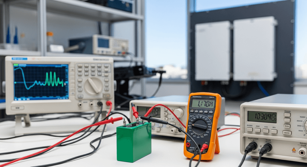
To truly grasp the necessity of a master-slave BMS, we must first benchmark the underlying physics. A parallel battery array is governed by Kirchhoff’s Current Law, which dictates that the total current entering a junction must equal the total current leaving it. In a perfect world, if you parallel four 100Ah batteries, a 100A discharge would draw exactly 25A from each. However, we operate in the real world, where no two batteries are identical. Even minute variations in internal resistance (measured in milliohms, mΩ), cable length, or terminal torque can create preferential paths for electron flow. The battery with the lowest resistance will work the hardest, discharging faster and charging faster than its peers. This is the genesis of imbalance.
This imbalance has profound implications for the battery’s chemistry, particularly in Lithium Iron Phosphate (LiFePO4) cells, the standard for stationary storage. The process of charging and discharging involves the intercalation (insertion) and deintercalation (removal) of lithium ions from the graphite anode and LiFePO4 cathode. When one pack is consistently over-discharged, its cell voltage drops dangerously low, potentially leading to the dissolution of the copper anode current collector, an irreversible failure. Conversely, the pack that charges fastest can be pushed into an over-voltage state, causing lithium plating on the anode surface. This plating reduces capacity and can grow into dendrites, which may pierce the separator and cause an internal short circuit—the precursor to thermal runaway. A simple, non-communicating BMS on each battery can only protect itself; it cannot coordinate with the others to prevent systemic imbalance. For more on this chemistry, our guide to LiFePO4 solar batteries offers a deeper dive.
Component Synergy: The Calibrated Handshake
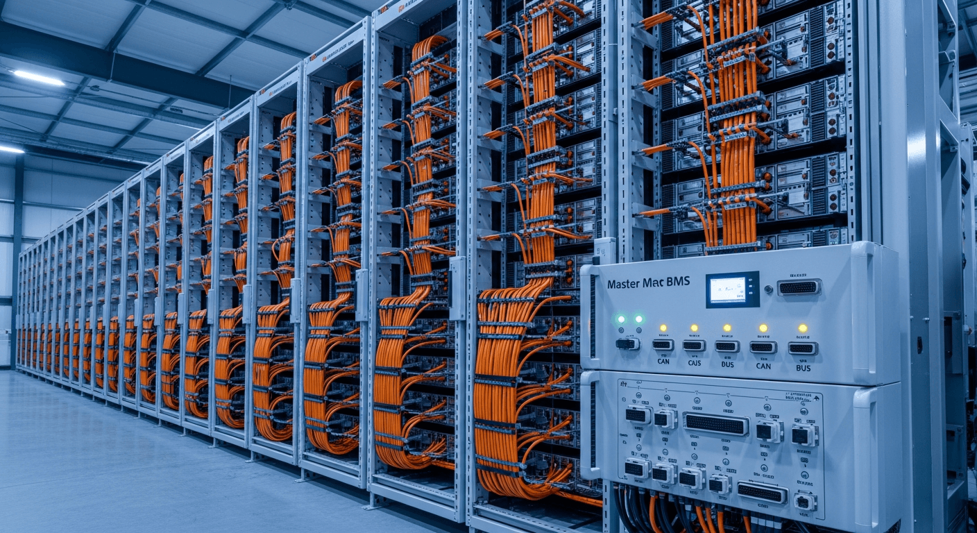
The master-slave topology solves this by establishing a strict hierarchy of control. Each individual battery pack has its own “slave” BMS, responsible for monitoring its own cell voltages, temperatures, and local state of charge (SOC). These slaves, however, do not act independently. They report their data packets, typically every 250-500 milliseconds, to a single “master” BMS. This master unit is the system’s central processor.
The master BMS performs three critical functions:
- Data Aggregation: It collects telemetry from all slave units, building a complete, real-time picture of the entire array. It knows the hottest cell, the lowest voltage cell, and the state of health (SOH) of every pack.
- Unified Decision-Making: Based on this aggregated data, it calculates a single, unified, and safe operating envelope for the entire bank. It determines the maximum allowable charge current, maximum discharge current, and overall bank SOC.
- External Communication: This is the crucial handshake. The master BMS communicates this unified status to the system’s inverter/charger and MPPT solar controller, typically via a CAN bus or RS485 protocol. The inverter no longer sees multiple disparate batteries; it sees one large, intelligent battery and obeys the master BMS’s commands. This prevents the inverter from pushing a charge current that the weakest battery in the array cannot handle, thereby protecting the entire investment and maximizing solar inverter efficiency and photon harvesting from the panels, a field where NREL Best Research-Cell Efficiency charts show continuous progress.
Engineering Math & Sizing for Parallel Arrays
Properly sizing your battery bank is the first step in ensuring long-term performance. The core formula to determine your required energy capacity is a crucial starting point, but understanding the variables is what separates an amateur from a professional installation.
Formula for Battery Bank Sizing:
Total Capacity (kWh) = (Average Daily Energy Load (kWh) × Days of Autonomy) / (Battery Depth of Discharge (DoD) × System Round-Trip Efficiency)
- Average Daily Energy Load (kWh): This is the total energy your property consumes in 24 hours. It’s critical to analyze your load profile, distinguishing between continuous loads (refrigerators, servers) and intermittent high-draw loads (well pumps, power tools). A detailed load analysis is a cornerstone of any serious off-grid solar kit design.
- Days of Autonomy: This buffer is your system’s resilience against low-sun periods (e.g., cloudy or stormy weather). For critical off-grid applications, 2-3 days is the standard. For grid-tied systems focused on time-of-use arbitrage, this may be less than 1.
- Depth of Discharge (DoD): This is how much of the battery’s capacity you plan to use. For LiFePO4, 80% is a conservative standard that yields a high cycle life. Discharging to 100% will significantly reduce the battery’s lifespan.
- System Round-Trip Efficiency: Energy is lost during storage and retrieval. This accounts for losses in the battery, inverter, and wiring. A typical value for a modern LiFePO4 system is 85-95%. You can learn more in our guide to round-trip efficiency.
Once you have the total kWh, you can determine the number of parallel batteries needed. For example, a 20 kWh requirement using 5.12 kWh batteries would necessitate 4 units in parallel. This is the point where implementing one of the robust BMS communication protocols for parallel battery configurations becomes absolutely essential for system health. A proper DIY solar panel installation must account for this from the initial design phase.
Master Comparison: Leading BMS-Enabled Battery Modules
To benchmark the market, we’ve compiled a comparison of leading battery modules designed for parallel operation. The Levelized Cost of Storage (LCOE) is a critical metric, calculated as the total system cost divided by the total energy throughput over its warranted life, providing a true “apples-to-apples” cost per kWh.
| Model | Communication Protocol | Max Parallel Units | LCOE (Est. $/kWh) | Cycles @ 80% DoD | Warranty (Years) |
|---|---|---|---|---|---|
| SolarKiit SK-4850 | CAN & RS485 (Selectable) | 64 | $0.09 | 8,000 | 15 |
| Enphase IQ 5P | Proprietary CAN | 16 | $0.12 | 6,000 | 15 |
| Tesla Powerwall 3 | Proprietary CAN | 4 | $0.14 | Unlimited (SOH Guarantee) | 10 |
| Victron Lynx Smart BMS | VE.Can & Bluetooth | System Dependent | $0.11 (with Victron batts) | 7,000 | 10 |
| Pylontech US5000-C | CAN & RS485 | 16 | $0.10 | 6,000 | 10 |
Regulatory Compliance & Safety Protocols for 2026
Deploying a parallel battery array is not just a technical challenge; it is a regulatory one. As energy storage becomes more prevalent, authorities having jurisdiction (AHJs) are strictly enforcing safety standards. A system without certified, communicating BMS architecture will not pass inspection.
NEC 2026 and UL 9540: The Gold Standards
The National Electrical Code (NEC), particularly Article 706 for Energy Storage Systems, provides the rulebook for safe installation. We anticipate the 2026 revision of the NFPA 70: National Electrical Code will place even greater emphasis on system-level control and rapid shutdown capabilities. A master BMS is the only practical way to implement requirements like NEC 706.15, which mandates a method to rapidly de-energize the system for first responders. The master BMS can receive a shutdown signal and command the contactors in every slave unit to open simultaneously.
However, the most critical standard is UL 9540, the Standard for Safety for Energy Storage Systems and Equipment. This is not a battery standard; it is a system standard. It validates that the entire assembly—batteries, BMS, and inverter—functions together safely. A key component of this is the UL 9540A test method, which evaluates thermal runaway fire propagation. A system with a master-slave BMS is designed to pass this test. If one battery pack enters thermal runaway, the master BMS will detect the anomaly, isolate that pack by opening its contactors, and prevent the failure from cascading to adjacent packs. This containment strategy is impossible without high-speed, reliable communication. For questions about certifying your system, please contact our engineering team. Leading certification bodies like UL Solutions (Solar Safety) are the gatekeepers for market access.
Fire Safety and NFPA 855
NFPA 855, the Standard for the Installation of Stationary Energy Storage Systems, governs the physical installation, including spacing, ventilation, and fire suppression. While these are passive measures, the BMS is the active, preventative measure. By meticulously managing cell temperatures and preventing overcharging, a master-slave BMS mitigates the root causes of thermal events. It is the first and most important line of defense, ensuring that passive fire safety measures are a last resort, not an inevitability. This level of safety is paramount whether you’re building a large utility-scale array or a simple portable power station.
The Pillar FAQ: Advanced Engineering Questions
1. How does a master-slave BMS topology prevent cascading failure in a large parallel LiFePO4 array?
A master-slave BMS prevents cascading failure through high-speed detection and electromechanical isolation. The system’s strength lies in its ability to act surgically. When a slave BMS detects a critical anomaly in its pack—such as a cell voltage exceeding its safe limit or a rapid temperature rise indicative of an internal short—it sends an emergency flag to the master BMS.
- Detection: The master BMS, which is constantly polling all slaves, immediately registers this flag.
- Decision: Its logic dictates that this pack is a threat to the entire array.
- Isolation: The master sends a direct command to the faulty slave pack’s BMS to open its main contactor(s), physically disconnecting it from the parallel DC bus.
- System Response: Simultaneously, the master BMS recalculates the array’s total safe operating envelope (e.g., reducing the max charge/discharge current) and updates the inverter. This prevents the remaining healthy packs from being overloaded. This entire process happens in milliseconds, long before a thermal event can propagate to neighboring packs.
2. What is the functional difference between CAN bus and RS485 for BMS communication, and which is superior for high-EMI environments?
CAN bus is functionally superior for high-EMI environments due to its differential signaling, message-based arbitration, and robust error-checking framework. While both are differential pair protocols, their implementation differs significantly.
- RS485 (Recommended Standard 485): A simple, character-based physical layer protocol. It’s effective and inexpensive but relies on the application layer (the software) to handle message collision and error checking. In a high-noise environment like a power electronics cabinet, this can lead to corrupted data packets if the software’s error handling isn’t perfect.
- CAN bus (Controller Area Network): A more advanced, message-based protocol. It was designed for the automotive industry, an environment with extreme electrical noise. It features collision detection and non-destructive arbitration, where higher-priority messages (like a thermal warning) automatically win bus access. Its hardware-level CRC (Cyclic Redundancy Check) ensures data integrity. This makes it the definitive choice for mission-critical systems like a battery power station.
3. Can you mix batteries of different ages or State of Health (SOH) in a parallel array with a sophisticated master-slave BMS?
No, this is strongly discouraged from an engineering standpoint, even with an advanced BMS. While a master-slave BMS can manage the imbalance, it cannot eliminate the fundamental performance bottleneck created by the weakest battery. The entire array’s performance is limited by its weakest link.
- Discharge Bottleneck: During discharge, the older battery with higher internal resistance will contribute less current. To meet the load demand, the newer batteries must work harder, accelerating their degradation to match the older pack.
- Charge Bottleneck: During charging, the older battery with lower capacity will reach its full charge voltage first. The master BMS will be forced to command the inverter to stop or reduce the charge current to protect this single pack, leaving the newer, larger-capacity batteries only partially charged.
- ROI Impact: You effectively negate the superior capacity and SOH of your new batteries, failing to achieve the expected performance and shortening the lifespan of your entire investment. Always parallel batteries of the same model, age, and batch.
4. How does the master BMS calculate a unified State of Charge (SOC) for the entire bank from disparate slave readings?
The master BMS calculates a unified SOC using a capacity-weighted average of all slave packs, which is then continuously calibrated against system-level coulomb counting. It’s a two-pronged approach to ensure accuracy.
- Weighted Averaging: The master doesn’t just average the SOC percentages. It polls each slave for its current SOC and, crucially, its calculated State of Health (SOH), which represents its actual remaining capacity. The formula is:
SOC_Array = Σ(SOC_slave_i × SOH_slave_i) / Σ(SOH_slave_i). This gives more weight to the healthier, higher-capacity packs. - Coulomb Counting Calibration: The master BMS also has its own current sensor (a hall-effect sensor or shunt) on the main DC bus. It tracks every amp-hour that enters and leaves the entire array. This “coulomb counting” provides a macro-level view of the SOC. The master BMS periodically uses this data to calibrate the individual SOC readings from the slaves, correcting for any drift over time. This is a core principle of a well-designed portable power system.
5. What is the role of active balancing versus passive balancing in a master-slave system, and how does it impact ROI?
Active balancing significantly improves ROI by increasing usable capacity and extending cycle life, whereas passive balancing is a simpler, less efficient method of maintaining cell equilibrium. The master BMS commands the balancing strategy, but the method used has a direct financial impact.
- Passive Balancing: When a cell reaches its top charge voltage before others, the slave BMS activates a resistor to bleed off the excess charge as heat. This is wasteful. The total charge current must be reduced to the rate the weakest cell can handle, extending charge times and increasing energy losses.
- Active Balancing: This method uses small DC-to-DC converters to actively shuttle energy from the highest-charged cells to the lowest-charged cells. Instead of wasting energy as heat, it redistributes it. This allows the entire pack to charge faster and enables the system to access more of its total stored energy on each cycle. Over thousands of cycles, this increased efficiency and usable capacity directly translates to a lower LCOE and a higher return on investment, which is the ultimate goal when selecting BMS communication protocols for parallel battery configurations.
📥 Associated Resource:

El Kouriani Abde Civil Engineer & Founder of SolarKiit
El Kouriani Abde is a seasoned Civil Engineer and Project Manager with over 21 years of field experience. As the founder and publisher of SolarKiit.com, he leverages his deep technical background to simplify complex renewable energy concepts. His mission is to provide homeowners and professionals with accurate, engineering-grade guides to maximize their solar investments and achieve energy independence.