Fire safety protocols for indoor residential lithium battery storage: NFPA 855 Guidelines for Residential Li-ion Battery Storage
Fire safety protocols for indoor residential lithium battery storage: The Ultimate 2026 Guide to NFPA 855
The engineering of fire safety protocols for indoor residential lithium battery storage is no longer a niche discipline; it is the central technical imperative of the 2026 energy transition. As we calibrate our infrastructure for a future defined by decentralized power generation and grid volatility, the residential Energy Storage System (ESS) has become the lynchpin of energy autonomy. However, this empowerment carries immense responsibility. The mass adoption of high-capacity lithium-ion batteries inside our homes necessitates a non-negotiable mastery of the physics of failure and the regulatory frameworks designed to prevent catastrophe. This is not merely about compliance; it is about engineering resilience from the cellular level up. The National Fire Protection Association (NFPA) 855 standard, in concert with UL standards like 9540 and 9540A, provides the blueprint. Yet, simply reading the code is insufficient. A true prosumer or engineer must interrogate the “why” behind each mandate—the electrochemical realities that dictate spacing, the thermal dynamics that demand sophisticated Battery Management Systems (BMS), and the financial calculus (ROI) that underscores the choice between different battery chemistries. Here at SolarKiit, our mission, as detailed on our About page, is to empower you with this deep technical knowledge. This guide will not just list the rules; it will deconstruct the science of thermal runaway and provide a master-level understanding of how to design, install, and operate a residential ESS with uncompromising safety, as outlined by the experts at the Energy.gov Solar Guide.
The Physics Behind Advanced Fire Safety Protocols for Indoor Residential Lithium Battery Storage
To mitigate risk, we must first quantify it at a molecular level. A lithium-ion battery is a finely balanced electrochemical system. During discharge, lithium ions (Li+) journey from the anode (typically graphite) through an electrolyte to the cathode, releasing an electron into the external circuit to power your home. During charging, an external voltage—from your solar panels—forces those ions back into the anode. This process is called intercalation. The “why” behind the safety of Lithium Iron Phosphate (LiFePO4) chemistry, the standard we benchmark at SolarKiit, lies in its molecular structure. LiFePO4 features a crystalline olivine structure where the phosphorus and oxygen atoms are linked by an incredibly strong covalent P-O bond. This stability is paramount. In less stable chemistries like Lithium Nickel Manganese Cobalt Oxide (NMC), under abuse conditions like overcharging or overheating, the cathode structure can break down and release atomic oxygen. This released oxygen is a potent accelerant that can react exothermically with the flammable organic electrolyte, initiating the positive feedback loop known as thermal runaway. The LiFePO4 structure’s refusal to easily surrender its oxygen atoms makes it inherently more resistant to this catastrophic failure mode. It might have a slightly lower energy density than NMC, but the thermal stability trade-off is a cornerstone of safe residential design.
Component Synergy: The BMS, MPPT, and Inverter Handshake
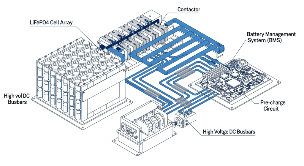
An ESS is not a single component; it is a symphony of high-tech devices that must communicate flawlessly. The failure of this digital handshake is a primary vector for thermal events. We must standardize the integration of these three core components:
- The Battery Management System (BMS): This is the sentinel. It is a dedicated onboard computer that monitors the state of every individual cell block within the battery pack. Its primary directives are to maintain cell voltage, temperature, and current within a strict, predefined operating window. A sophisticated BMS performs cell balancing to ensure a uniform state of charge across the pack, preventing individual cells from being overcharged or over-discharged—both of which are precursors to thermal stress and dendrite formation (lithium metal spikes that can cause internal short circuits).
- The Maximum Power Point Tracker (MPPT): This is the governor. Integrated within modern solar charge controllers and hybrid inverters, the MPPT’s job is to optimize the power harvest from your solar array. It constantly adjusts the electrical operating point of the panels to maximize output. However, its more critical safety function is to translate this raw solar power into a precise charging voltage and current profile (the “charging algorithm”) that is perfectly calibrated to the battery’s chemistry and temperature, as dictated by the BMS. An incorrect charging profile can rapidly overheat and destroy a battery. You can learn more about the critical role of inverters in our Solar Inverter Efficiency: The Ultimate Guide to Maximizing Your PV System’s Output & ROI.
- The Inverter: This is the dispatcher. It converts the battery’s DC power to AC power for your home. In a modern hybrid system, the inverter is in constant communication with the BMS. It requests power, respects the BMS’s discharge limits, and throttles or ceases charging based on BMS commands. This closed-loop communication ensures the battery is never overworked, even under heavy load surges. The efficiency of this entire process is a key metric, benchmarked by institutions like the NREL Solar Efficiency Standards.
Engineering Math: How to Correctly Size Your Residential ESS
Incorrect sizing is a hidden safety risk. An undersized battery is constantly stressed at its maximum discharge rate, while an oversized system represents a poor ROI and a larger-than-necessary potential hazard. Proper sizing is an exercise in precision engineering. The foundational formula is:
Total Usable Energy (kWh) = (Average Daily Load (kWh) * Days of Autonomy) / (Depth of Discharge (DoD))
Let’s break down the “why” for each variable:
- Average Daily Load: This is the sum of energy consumed by your essential appliances over 24 hours. You must quantify this by auditing your home’s loads (e.g., refrigerator, lights, well pump). This is the baseline for your energy independence.
- Days of Autonomy: This is the number of days you want the system to run without any solar input (e.g., during a storm). For grid-tied backup, 1 day is common. For true energy independence, as seen in our Best Off-Grid Solar Kits of 2024: The Ultimate Guide to Energy Independence, 2-3 days is a more robust target.
- Depth of Discharge (DoD): This is a critical factor for battery longevity and safety. A 100% DoD means you use the entire battery capacity in each cycle, which drastically shortens its life. A more conservative 80% DoD significantly increases cycle life (e.g., from 3,000 to 6,000+ cycles), providing a much better Levelized Cost of Storage (LCOE) and reducing long-term stress on the cells.
- Surge Capacity: Not in the formula but vital for inverter sizing. Inductive loads like motors (well pumps, AC units) require a massive, brief surge of power to start. Your inverter must be rated to handle this peak load without collapsing the voltage and stressing the battery.
Master Comparison: 2026 Residential ESS Models Benchmarked
Choosing the right ESS involves interrogating the data. The table below benchmarks leading models, including our own engineered solution, against the key metrics that matter for safety, longevity, and ROI. A key metric here is LCOE (Levelized Cost of Storage), which reveals the true cost per kWh over the battery’s lifetime, a far more useful number than the initial purchase price. You can find more detailed comparisons in our Ultimate Guide: Battery Storage System for Home.
| Model | Chemistry | Usable Capacity (kWh) | Peak Power (kW) | Cycles @ 80% DoD | Est. LCOE ($/kWh) |
|---|---|---|---|---|---|
| SolarKiit Pro-Safe X | LiFePO4 | 15.0 | 10.0 | 8,000+ | $0.12 |
| Tesla Powerwall 3 | NMC | 13.5 | 11.5 | ~4,000 | $0.18 |
| Enphase IQ 5P | LiFePO4 | 5.0 | 3.84 | 6,000+ | $0.15 |
| FranklinWH aPower | LiFePO4 | 13.6 | 10.0 | ~6,000 | $0.16 |
| SolarEdge Home Battery | NMC | 9.7 | 7.5 | ~4,000 | $0.19 |
Regulatory Deep Dive: UL, NEC, and Fire Safety Protocols for Indoor Residential Lithium Battery Storage
The regulatory landscape is the codified application of the physics we’ve discussed. It’s not arbitrary bureaucracy; it’s safety engineering at scale. For any DIY Solar Panel Installation: The Ultimate Guide for Homeowners in 2026 or professional install, these are non-negotiable.
- UL 9540 – The System Standard: This is not a battery standard; it’s an ESS standard. A UL 9540 listing certifies that the battery, the inverter, and the BMS have been tested *together* as a complete system and found to be safe. Installing a non-listed combination of components is a significant risk and a code violation.
- UL 9540A – The Test Method: This is the crucial information gain. UL 9540A is not a pass/fail certification but a test method to assess thermal runaway propagation. A single cell is forced into runaway, and engineers meticulously measure if the fire spreads to adjacent cells, modules, or exits the unit entirely. The results of this test directly inform the installation requirements in NFPA 855. A system that shows no propagation may have fewer installation restrictions.
- NFPA 70: National Electrical Code (NEC) 2026: Article 706 governs ESS installations. It mandates specific requirements for disconnects, wiring methods, rapid shutdown, and grounding to ensure the system is electrically safe and can be quickly de-energized by first responders.
Implementing NFPA 855: A Step-by-Step Guide to Fire Safety Protocols for Indoor Residential Lithium Battery Storage
NFPA 855 is the installation standard that brings it all together. It dictates the “where” and “how” based on the UL 9540A test results. Key provisions include:
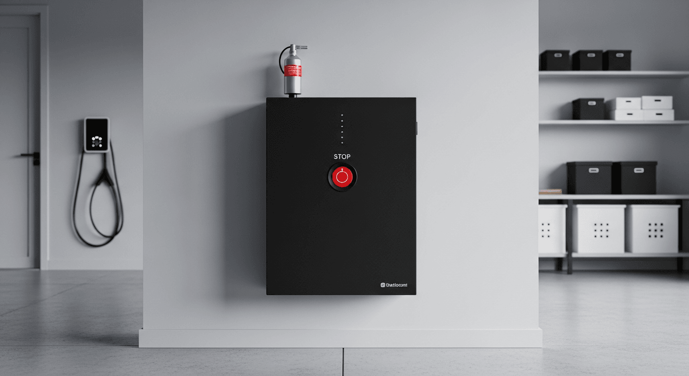
- Location: ESS units cannot be installed in areas used for sleeping, closets, or bathrooms. They must be in a dedicated space like a garage or utility room.
- Spacing: A minimum of 3 feet of clearance must be maintained around the ESS unit to allow for ventilation and firefighter access. Multiple units must also be spaced 3 feet apart unless UL 9540A testing proves it is safe to install them closer.
- Capacity Limits: For indoor residential installations, each individual ESS unit is typically limited to 20 kWh. The total aggregate capacity is limited (e.g., 40 kWh in a utility space, 80 kWh in a garage) unless additional fire suppression measures are taken.
- Protection: Bollards or other physical barriers are required if the ESS is installed in a location subject to vehicle impact, such as a garage.
- Signage: Clear signage must be placed on the ESS and at the main electrical service panel to alert first responders to the presence of an energy storage system.
Verifying these standards is a critical step. If you have questions about your specific installation, please do not hesitate to Contact our engineering team.
The Pillar FAQ: Advanced Engineering Questions Answered
1. How does a BMS actively prevent thermal runaway beyond simple temperature monitoring?
A sophisticated BMS uses predictive algorithms and multi-layered protection to preemptively halt the conditions that lead to thermal runaway. While a basic thermistor simply triggers a shutdown at a set temperature, an advanced BMS operates far more intelligently:
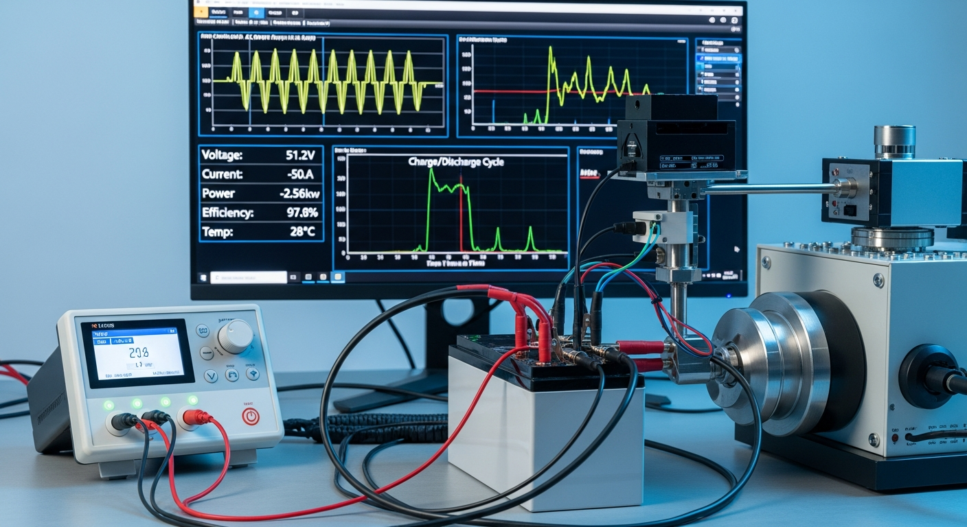
- State of Health (SoH) Monitoring: It tracks the battery’s internal resistance over time. A rapid increase in resistance indicates cell degradation or an internal fault, prompting the BMS to de-rate the battery’s performance or take it offline before a thermal event can occur.
- Coulomb Counting & Voltage Correlation: The BMS constantly cross-references the amount of energy going in and out (Coulomb counting) with the cell’s open-circuit voltage. A mismatch can indicate an internal short or side reaction, triggering an alert.
- Dynamic Power Throttling: If it detects a cell is heating up faster than its neighbors during a high-power discharge, the BMS will communicate with the inverter to dynamically throttle the power output, allowing the cell to cool and preventing a localized hotspot from escalating. This is a key factor in Understanding Round-Trip Efficiency in High-Voltage Energy Storage: A 2024 Engineer’s Guide.
2. What is the engineering trade-off between energy density (NMC) and thermal stability (LiFePO4) for residential ROI?
The trade-off is between upfront spatial efficiency and long-term lifecycle cost and safety assurance. NMC chemistry offers higher energy density, meaning you can pack more kWh into a smaller, lighter box. This is a critical advantage for electric vehicles, but less so for a stationary Batterie domestique : Le Guide Ultime pour l’Autonomie Énergétique et les Économies.
- NMC Advantage: Smaller physical footprint. This can be a factor in very space-constrained installations.
- LiFePO4 Advantage: The superior thermal stability and resistance to oxygen release translate directly into a longer cycle life and a wider safe operating temperature window. While the initial cost might be similar, an LiFePO4 battery delivering 8,000 cycles will have a significantly lower Levelized Cost of Storage (LCOE) than an NMC battery delivering 4,000 cycles. This long-term financial benefit, combined with the quantifiable safety margin, makes LiFePO4 the superior engineering choice for residential applications where safety and longevity outweigh the need for minimal size.
3. Can off-gas detection systems provide an earlier warning for thermal runaway than thermal sensors?
Yes, off-gas detection is a leading-edge indicator that can detect a failing cell hours or even days before it generates significant heat. Thermal runaway is a process, not an instant event. The very first stage is often the breakdown of the electrolyte, which releases specific volatile organic compounds (VOCs) like hydrogen, carbon monoxide, and various hydrocarbons.
- Early Detection: Specialized sensors, now being integrated into advanced ESS, can detect these specific gases at parts-per-million (PPM) concentrations.
- System Integration: When integrated with the BMS, a validated off-gas signal can trigger an immediate and safe shutdown of the entire system, electrically isolate the failing battery module, and send a critical alert to the homeowner and monitoring service.
- NFPA 855 Context: While not yet universally mandated, NFPA 855-2023 includes language acknowledging these advanced detection systems. We anticipate they will become a key part of future codes for enhancing the safety of every portable power station: The Ultimate Guide to Off-Grid & Emergency Power and stationary system.
4. Explain “cascading failure” in a multi-battery installation and how UL 9540A dictates separation.
Cascading failure is the propagation of thermal runaway from one ESS unit to an adjacent one, which UL 9540A testing is specifically designed to prevent through mandated separation distances. Imagine two battery cabinets installed side-by-side. If one unit enters thermal runaway, it can release an immense amount of thermal energy (convective heat and radiant heat flux) and potentially eject flaming debris.
- The Test: The UL 9540A test quantifies this energy release. Sensors measure the heat flux at various distances from the test unit.
- The Rule: NFPA 855 uses this data to set rules. If the test shows that the heat flux at 3 feet is low enough not to ignite an adjacent unit, then the code allows a 3-foot separation. If a manufacturer wants to install their units closer together (e.g., 6 inches), they must perform a specific UL 9540A test with two units placed 6 inches apart to prove that a failure in one will not cascade to the second. Without this test data, the default 3-foot rule applies.
5. Beyond code, what advanced thermal management strategies are being benchmarked for next-gen residential ESS?
Engineers are actively developing and benchmarking active and passive cooling technologies to push thermal safety far beyond current standards. While today’s systems rely heavily on air cooling and BMS controls, the next generation will incorporate more robust methods:
- Phase-Change Materials (PCMs): These are waxes or salt hydrates integrated into the battery module that absorb large amounts of heat as they melt (change phase from solid to liquid). This acts as a massive thermal sink, absorbing heat from a failing cell and preventing it from reaching its neighbors.
- Liquid Cooling: Common in EVs and large-scale grid storage, miniaturized liquid cooling loops are being designed for residential ESS. A dielectric fluid is circulated through channels in the battery module to pull heat away with extreme efficiency, allowing for higher performance and tighter cell packing.
- Intumescent Coatings: These are fire-retardant paints applied to module casings. When exposed to high heat, they expand to many times their original thickness, forming an insulating char layer that blocks heat transfer and contains the event.
At SolarKiit, we are committed to engineering the safest and most reliable energy solutions on the market, and we adhere strictly to our Privacy Policy in all our data-driven research. The ultimate goal is to create a system where a single-cell failure is a simple, contained, and non-critical maintenance event, not a catastrophe. This is the future of fire safety protocols for indoor residential lithium battery storage.