home storage battery : Guide d’ingénieur 2026 pour l’autonomie & la rentabilité
As we advance into 2026, the paradigm of residential energy is undergoing a fundamental engineering-led transformation. The era of passive energy consumption is being supplanted by a model of active energy management, with the home storage battery at its epicenter. This shift is driven by a confluence of economic and technical catalysts: volatile grid pricing, the sunsetting of favorable net metering policies like NEM 2.0, and a collective demand for greater energy resilience against climate-induced grid instability.
For the discerning engineer and prosumer, a home battery is no longer a luxury but a strategic asset. It functions as a temporal energy buffer, decoupling household energy consumption from real-time grid generation. This allows for sophisticated energy arbitrage—storing low-cost off-peak or solar-generated energy and dispatching it during high-cost peak hours. This maximizes the return on investment (ROI) of a photovoltaic (PV) system and provides a critical layer of autonomy.
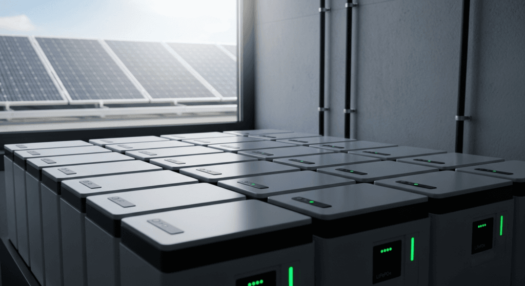
The 2026 market is characterized by mature Lithium Iron Phosphate (LiFePO4) technology, offering unprecedented safety and cycle life, and the nascent integration of intelligent software. These systems now leverage predictive algorithms, weather forecasting, and user consumption patterns to optimize charge and discharge cycles. The objective has evolved beyond simple backup power; it is now about achieving a calculated, profitable, and resilient energy independence. This guide provides the requisite technical framework for specifying and deploying such a system.
Deep Technical Analysis: Engineering a Resilient Home Energy System
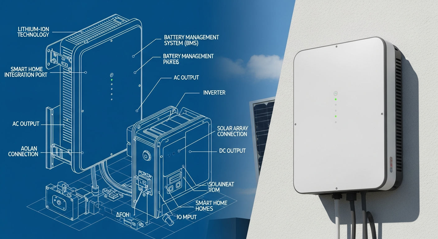
A comprehensive understanding of a home battery system requires a granular analysis of its constituent components and the physical principles governing their interaction. The goal is to create a balanced, efficient, and correctly sized system that meets specific load requirements while minimizing energy losses and maximizing component lifespan. This is a system engineering challenge, not merely a component selection exercise.
The Physics of DC-to-AC Energy Conversion and Storage
The journey of a solar electron from a PV panel to a household appliance involves multiple conversion stages, each with an associated efficiency loss. Understanding this cascade is critical for accurate system sizing. The process begins with the photovoltaic effect in the solar panels, which generate Direct Current (DC) electricity. The voltage and current produced are variable, dependent on solar irradiance and cell temperature.
This variable DC power is then routed to a Maximum Power Point Tracking (MPPT) charge controller. The MPPT’s function is to algorithmically adjust its input impedance to find the optimal voltage (Vmp) and current (Imp) at which the PV array produces maximum power. By 2026, MPPT controllers consistently achieve efficiencies exceeding 99%, making them a near-lossless component in the charging path.
The regulated DC output from the MPPT charges the battery bank. The battery stores energy chemically. During discharge, this DC power flows to an inverter. The inverter’s primary role is to convert the battery’s stable DC voltage (e.g., 48V nominal) into a stable 120/240V, 60Hz Alternating Current (AC) waveform, suitable for powering household appliances. This DC-to-AC conversion is the site of the most significant potential power loss and waveform quality determination.
2026 Efficiency Benchmarks and Component Specifications
System performance is the product of the efficiencies of its parts. In 2026, the expected benchmarks for high-quality residential systems are stringent:
- Photovoltaic Panels: Monocrystalline TOPCon (Tunnel Oxide Passivated Contact) or HJT (Heterojunction) cells are the standard, with commercial efficiencies ranging from 23% to 25%. Their superior temperature coefficient and low-light performance are critical for consistent year-round generation.
- Battery Chemistry: LiFePO4 (Lithium Iron Phosphate) is the dominant chemistry. Its key metric is Round-Trip Efficiency (RTE), which measures the energy out versus energy in. For 2026-era LiFePO4, RTE is typically 92% to 95%. This means for every 10 kWh of energy stored, 9.2 to 9.5 kWh is retrievable.
- Inverter Technology: Pure Sine Wave inverters are mandatory for modern electronics. Their efficiency in 2026 stands at 95% to 97% at peak load. It is crucial to analyze the efficiency curve, as performance can drop at very low or very high loads relative to the inverter’s nominal rating.
The total system efficiency is a product of these values. For a DC-coupled system (where PV, battery, and inverter share a common DC bus), a realistic end-to-end efficiency from PV panel to AC outlet is approximately: 0.99 (MPPT) * 0.95 (Battery RTE) * 0.96 (Inverter) ≈ 90%. For an AC-coupled system, where a grid-tie inverter’s AC output is converted back to DC to charge the battery, an additional conversion loss is introduced, often reducing total efficiency.
Load Calculation and Strategic Sizing
Sizing a battery system is the most critical engineering task. Undersizing leads to insufficient autonomy and premature battery degradation from excessive cycling. Oversizing results in unnecessary capital expenditure and diminished ROI. The process begins with a meticulous load analysis.
First, create a load table listing all critical and non-critical appliances. For each, document its power consumption in watts (W) and estimated daily usage in hours (h). The product gives daily energy consumption in watt-hours (Wh). Summing these values for all appliances yields the total daily energy requirement in kWh. For example, a refrigerator (150W, running 8h/day) consumes 1.2 kWh/day. A full household might average 15-30 kWh/day.
The core sizing formula is:
Required Battery Capacity (kWh) = (Total Daily Load [kWh] * Days of Autonomy) / (Max Depth of Discharge [DoD] * Temperature Derating Factor * System Efficiency)
Let’s deconstruct this:
- Days of Autonomy: The number of consecutive cloudy days the system must operate without solar input. A typical value is 1 to 3 days.
- Depth of Discharge (DoD): For LiFePO4, a DoD of 80-90% is standard practice to maximize cycle life. Discharging to 100% is possible but will reduce the total number of cycles.
- Temperature Derating: LiFePO4 performance degrades in extreme cold (below 0°C) and heat (above 45°C). A derating factor (e.g., 0.9 for a hot climate) must be applied based on the installation environment’s temperature profile.
- System Efficiency: The overall efficiency calculated earlier (approx. 90%).
For a home using 20 kWh/day, desiring 2 days of autonomy with a LiFePO4 battery (90% DoD) in a temperate climate (no derating), the calculation would be: (20 kWh * 2) / (0.90 * 1.0 * 0.90) ≈ 49.4 kWh of nominal battery capacity required. This engineering-based approach ensures the system performs as specified under real-world conditions.
Engineering Specifications & 2026 Innovations
The 2026 home energy storage market is defined by sophisticated, integrated systems and incremental but significant advances in cell and material science. The focus has shifted from raw capacity to intelligent control, modularity, and safety. Leading manufacturers are differentiating through software ecosystems and hardware interoperability.
Dominant Chemistries and Cell Formats
LiFePO4 remains the undisputed leader for stationary residential storage. Its key advantages are its exceptional thermal stability, making it highly resistant to thermal runaway, and its long cycle life, with premium cells rated for over 6,000-10,000 cycles at 80% DoD. This translates to a usable lifespan of 15-20 years, aligning perfectly with the lifespan of a PV array. The cells are typically prismatic, allowing for high energy density in a compact, stackable form factor.
While LiFePO4 dominates, Sodium-Ion (Na-ion) batteries are emerging as a viable, lower-cost alternative for 2026. Their primary appeal is the use of abundant and inexpensive raw materials (sodium instead of lithium). While their energy density is lower than LiFePO4, their excellent cold-weather performance and comparable safety profile make them a strong contender for budget-conscious or large-scale stationary storage where space is less of a constraint.
Brand-Specific Architectures: Integrated vs. Modular
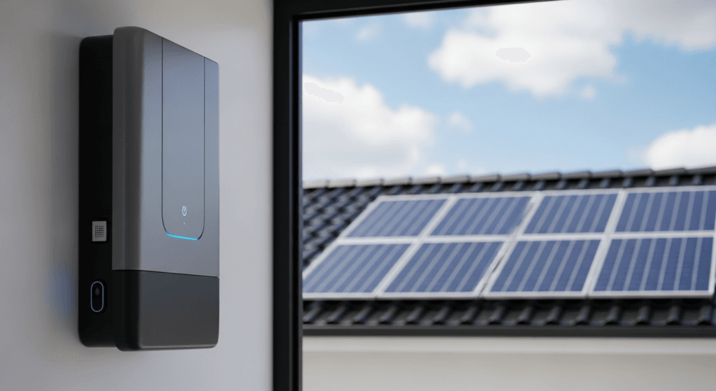
System architecture is a key differentiator. Tesla’s Powerwall 3 exemplifies the integrated approach. It combines the battery, a high-power 11.5 kW inverter, and a solar charge controller into a single, sleek unit. This simplifies installation and ensures seamless component communication but offers less flexibility for customization or piecemeal upgrades.
In contrast, brands like EcoFlow and Bluetti champion a modular, scalable architecture. The EcoFlow DELTA Pro Ultra system, for instance, allows users to stack battery packs (e.g., 6 kWh each) to achieve a desired capacity up to 90 kWh. This is paired with a separate inverter unit. This “building block” approach provides greater flexibility in sizing and allows for future expansion as energy needs grow. It is particularly advantageous for complex off-grid or phased installations.
Victron Energy continues to serve the high-end, custom-build market. Rather than selling an all-in-one kit, Victron provides best-in-class individual components—MultiPlus inverters/chargers, SmartSolar MPPTs, and Cerbo GX system controllers. This allows an engineer to design a highly robust and bespoke system tailored to unique load profiles, such as those requiring 3-phase power or integration with a generator. This approach requires a higher level of design expertise but offers unparalleled control and reliability.
The Perovskite-Silicon Tandem Cell Influence
A key innovation on the generation side impacting storage is the commercialization of Perovskite-on-Silicon tandem solar cells. By 2026, these panels are reaching efficiencies of over 30% in lab settings and entering niche high-performance markets. Their enhanced spectral response, particularly in low-light conditions (early morning, late evening, cloudy days), extends the daily charging window for a battery system. This means a smaller PV array can potentially fully charge the same size battery, reducing upfront system cost and roof space requirements. The system’s charge controller must be able to handle the unique voltage and current characteristics of these advanced panels.
Technical Comparison of Leading 2026 Home Battery Systems
Selecting the right system requires a detailed comparison of key engineering metrics. The following table outlines the specifications for five representative models and system types available in 2026, highlighting the trade-offs between integrated, modular, and component-based solutions.
| Model / System | Nominal Capacity (kWh) | Chemistry | Cycle Life (@80% DoD) | Max Continuous Power (kW) | Round-Trip Efficiency | Key Engineering Feature |
|---|---|---|---|---|---|---|
| Tesla Powerwall 3 | 13.5 kWh | LiFePO4 | ~6000 | 11.5 kW | ~90% (System) | Fully integrated inverter; high power output. |
| EcoFlow DELTA Pro Ultra | 6 kWh (Scalable to 90 kWh) | LiFePO4 | ~6500 | 7.2 kW (Scalable to 21.6 kW) | ~94.5% (Battery only) | Highly modular and scalable; portable option. |
| Enphase IQ Battery 5P | 5.0 kWh (Scalable) | LiFePO4 | ~6000 | 3.84 kW (Scalable) | ~90% (System) | AC-coupled; integrates with Enphase microinverters. |
| Bluetti EP900 & B500 | 9.9 kWh (Scalable to 39.6 kWh) | LiFePO4 | ~7000 | 9.0 kW | ~93% (Battery only) | Split-phase 120/240V output from single unit. |
| Victron Custom System | User Defined | LiFePO4 (or other) | Depends on battery choice | User Defined (e.g., 3kW – 15kW+) | ~95% (Component dependent) | Ultimate customization for off-grid and complex loads. |
Safety Protocols and Governing Standards
The deployment of a high-voltage DC energy storage system within a residential environment necessitates uncompromising adherence to safety standards and electrical codes. A failure in design or installation can pose significant risks, including electrical shock and fire. Professional installation by a certified electrician is not just recommended; it is essential for safety, code compliance, and insurance validity.
Navigating the National Electrical Code (NEC)
In the United States, NEC Article 706 (formerly parts of 480) provides the primary framework for Energy Storage Systems (ESS). Key mandates include requirements for readily accessible disconnects for the battery and inverter, proper overcurrent protection (fuses or circuit breakers) rated for DC circuits, and specific signage indicating the presence of an ESS. Conductor sizing must account for voltage drop and ampacity, especially in long DC cable runs from the PV array.
NEC Article 705, “Interconnected Electric Power Production Sources,” is also critical. It governs how the system safely connects to the grid and the home’s load center (electrical panel). It mandates features like anti-islanding, where the inverter must automatically shut down during a grid outage to prevent back-feeding and protect utility workers. All components must be listed and labeled for their intended use.
Component Certification and Environmental Ratings
Beyond code, specific product certifications are paramount. UL 9540 is the benchmark safety standard for an entire ESS, covering the battery, inverter, and control software as an integrated unit. It evaluates thermal performance, electrical safety, and fault response. A UL 9540-listed system has been rigorously tested to work together safely. Additionally, the inverter must be certified to UL 1741, which covers inverters and converters used in distributed energy systems and includes the anti-islanding test protocols.
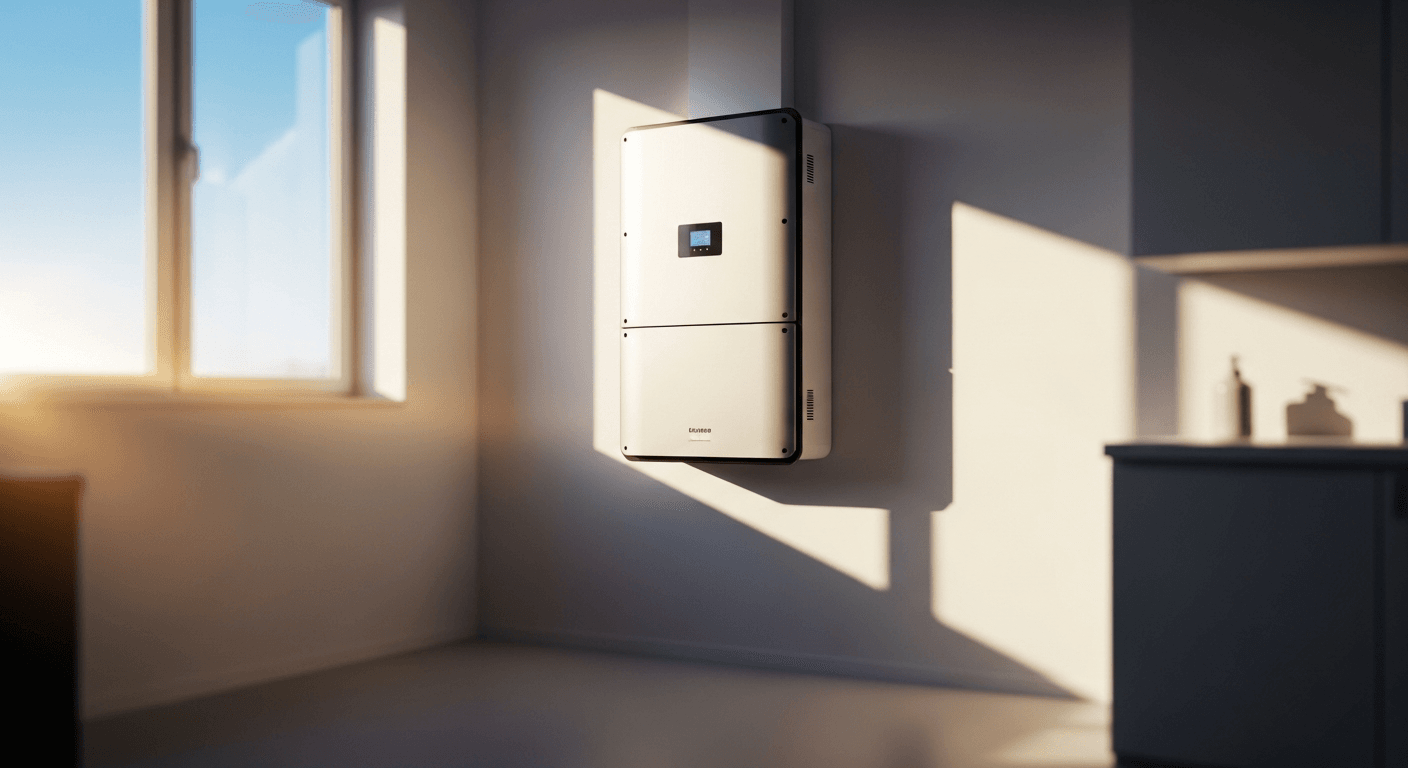
Environmental protection is quantified by the Ingress Protection (IP) rating. An IP65 rating ensures the enclosure is dust-tight and can withstand low-pressure water jets, making it suitable for many outdoor or garage installations. For more exposed locations, an IP67 rating is superior, certifying that the unit can be temporarily submerged in water without damage. The choice of IP rating must match the environmental conditions of the installation site.
Fire Safety and Thermal Management
While LiFePO4 chemistry is inherently safer than older lithium-ion formulations like NMC (Nickel Manganese Cobalt), thermal management remains a critical design consideration. All ESS must be installed with adequate clearance from combustible materials as specified by the manufacturer and local building codes. Proper ventilation is required to dissipate heat generated during high-power charging and discharging cycles. In enclosed spaces, active ventilation may be necessary to keep the ambient temperature within the battery’s operational window, preserving both performance and lifespan.
Pre-Installation Operational Checklist
A successful and safe installation begins with meticulous planning. This checklist is designed for the technically-minded homeowner or project manager to complete before any hardware is installed. It ensures all critical variables have been considered, preventing costly errors and ensuring system performance meets expectations.
- Complete Load Analysis: Have you created a detailed spreadsheet of all electrical loads, including their wattage, daily run time, and surge power requirements (for motors, pumps, etc.)?
- Define Autonomy Goal: Have you determined the required number of days of autonomy based on your location’s weather patterns and your personal risk tolerance for grid outages?
- Structural Assessment: Have you confirmed the mounting location (wall or floor) has the structural capacity to support the full weight of the battery system? A 20 kWh system can weigh over 400 lbs (180 kg).
- Verify Component Certifications: Have you confirmed that the chosen battery system is listed under UL 9540 and the inverter is listed under UL 1741? Do not accept uncertified components.
- Plan for Thermal Management: Does the installation location provide adequate ventilation and maintain an ambient temperature within the battery’s specified operating range (typically 0°C to 45°C)?
- Calculate Voltage Drop: For the DC wiring from the PV array to the charge controller/inverter, have you calculated the potential voltage drop to ensure it is below the recommended 2-3%? Use a voltage drop calculator and select the appropriate wire gauge.
- Review Local Codes and Permits: Have you consulted with your local building department to understand all permitting requirements and any specific local amendments to the NEC?
- Select a Certified Installer: Have you vetted and selected an electrician or solar installer with specific, verifiable experience and certification in installing energy storage systems?
Advanced Engineering FAQ
What is the real-world impact of inverter waveform (Pure Sine vs. Modified Sine) on sensitive electronics?
A Pure Sine Wave inverter produces an AC waveform that is identical to or cleaner than grid power. This is critical for modern electronics like variable-speed motors, medical equipment, and devices with AC-DC power bricks. A Modified Sine Wave, which has a blocky, stepped waveform, can cause these devices to run hotter, less efficiently, or fail entirely. It can also introduce audible buzzing in audio equipment. For a 2026-era home system, a Pure Sine Wave inverter is the only acceptable engineering choice.
How does voltage drop in long DC cable runs from the PV array impact system performance?
Voltage drop is a loss of electrical pressure (voltage) due to the resistance of the cable (Ohm’s Law: V=IR). In a solar installation, a long cable run from the PV array to the charge controller can cause significant voltage drop. If the voltage at the controller’s input terminals drops below its minimum operating threshold, it may fail to operate. Even if it operates, the power loss (P = V * I, so power loss is proportional to voltage drop) reduces the total energy harvested, directly impacting the system’s ROI. It is critical to mitigate this by using a sufficiently large wire gauge (e.g., AWG 4 or 2) or by designing the PV array for a higher string voltage, which reduces current for the same power level.
Can I AC-couple vs. DC-couple a battery to an existing grid-tie solar system, and what are the efficiency trade-offs?
Yes, both are common strategies. DC-coupling integrates the battery on the DC side of the system, before the main inverter. Solar energy flows through the charge controller to the battery and inverter with high efficiency. AC-coupling is used to retrofit a battery to an existing grid-tie system that already has its own microinverters or string inverter. The battery system has its own inverter/charger that takes AC power from the solar inverter, converts it to DC to charge the battery, and then converts it back to AC for use. This double conversion (AC -> DC -> AC) introduces an additional efficiency loss of 5-10% compared to a DC-coupled system. However, AC-coupling is often simpler and more cost-effective for retrofits.
How does temperature derating affect LiFePO4 battery performance and lifespan in extreme climates?
LiFePO4 batteries have a specific optimal operating temperature range. In high temperatures (e.g., above 45°C), the battery management system (BMS) will typically derate (reduce) the maximum charge and discharge current to prevent accelerated cell degradation and potential damage. This reduces the available power. In cold temperatures (below 5°C), the internal resistance of the cells increases, reducing efficiency and available power. Most BMS will prevent charging entirely below 0°C to avoid lithium plating, which permanently damages the cell. For installations in extreme climates, insulated enclosures or active heating/cooling systems are an essential engineering control to maintain battery health and performance.
What are the key considerations for integrating an EV charger with a home battery for V2H (Vehicle-to-Home) functionality?
Vehicle-to-Home (V2H) integration requires three key components: a bidirectional EV, a bidirectional DC charger, and a compatible home energy management system. The primary engineering consideration is communication protocol; the charger must be able to communicate with both the vehicle’s BMS and the home’s ESS controller to manage power flow. The home’s main electrical panel and the ESS inverter must be rated to handle the high power flow from the vehicle’s battery (often 10 kW or more). Finally, the system’s software must be sophisticated enough to make intelligent decisions about when to discharge the vehicle to power the home (e.g., during a grid outage or high-cost peak hours) without depleting the car’s battery below a user-defined threshold needed for driving.
📥 Associated Resource:

El Kouriani Abde Civil Engineer & Founder of SolarKiit
El Kouriani Abde is a seasoned Civil Engineer and Project Manager with over 21 years of field experience. As the founder and publisher of SolarKiit.com, he leverages his deep technical background to simplify complex renewable energy concepts. His mission is to provide homeowners and professionals with accurate, engineering-grade guides to maximize their solar investments and achieve energy independence.