Ultimate Guide: How to Fix LiFePO4 Battery Cell Imbalance in Solar Systems: A Complete 2026 Guide

How to fix LiFePO4 battery cell imbalance in solar systems: The Ultimate 2026 Comprehensive Guide
As the CTO of SolarKiit, I’m frequently asked by engineers and advanced prosumers about the single most critical factor impacting the longevity and return on investment (ROI) of a solar energy storage system. The answer isn’t the inverter or even the panels; it’s the granular health of the battery cells. Understanding how to fix LiFePO4 battery cell imbalance in solar systems is not just a maintenance task—it is the core engineering discipline that separates a system that lasts five years from one that exceeds its 15-year design life. In the 2026 energy landscape, where grid independence and decentralized power are paramount, the resilience of your battery bank dictates your energy security. Lithium Iron Phosphate (LiFePO4) has rightfully become the dominant chemistry for stationary storage due to its inherent safety and cycle life. However, its flat voltage curve, while beneficial for consistent power output, masks the early signs of cell imbalance, making proactive management essential. This guide moves beyond the superficial advice found elsewhere. We will dissect the physics, quantify the financial impact, and provide the engineering-grade procedures to diagnose, rectify, and prevent cell imbalance. At SolarKiit, our mission is to empower users with deep technical knowledge, and you can learn more about our engineering philosophy on our About page. This is not just a “how-to”; this is a masterclass in optimizing the heart of your solar power system for maximum performance and financial return.
The Deep Technical Dive: Physics, Chemistry, and Component Synergy
To truly grasp cell imbalance, we must first go beyond the macro view of a “battery” and into the microscopic world of electrochemistry and electron flow. A LiFePO4 battery is not a monolithic entity; it is a series-parallel array of individual cells, each with a nominal voltage of approximately 3.2V. The performance of the entire bank is dictated by its weakest cell. This is the fundamental principle that makes imbalance so destructive.
The Physics and Chemistry of a LiFePO4 Cell
At its core, a LiFePO4 cell operates through a process called intercalation. During discharge, lithium ions (Li+) travel from the graphite anode, through the electrolyte and separator, to the iron phosphate (FePO4) cathode. This migration releases an electron into the external circuit, creating the electrical current that powers your loads. During charging, an external voltage (from your solar panels via an MPPT controller) forces this process in reverse: Li+ ions are driven from the cathode back into the anode’s graphite lattice structure. The key is that the voltage of a cell is a direct proxy for its State of Charge (SOC), but only at the very top and bottom of the charge cycle. For over 80% of its capacity, the voltage curve is remarkably flat, hovering around 3.2V-3.3V.
This is where the problem begins. A cell with a slightly lower internal capacity or slightly higher internal resistance will behave differently. During a charging cycle, this “weaker” cell will reach its maximum voltage (typically ~3.65V) before the others. A sophisticated Battery Management System (BMS) will detect this and command the MPPT to stop charging the entire bank to prevent overcharging that single cell. The result? The rest of the cells are not fully charged. Conversely, during discharge, the same weak cell will hit the low-voltage cutoff (typically ~2.5V) first, causing the BMS to disconnect the load while the other cells still hold significant charge. This phenomenon, known as “voltage clamping,” effectively shrinks your usable battery capacity and accelerates the degradation of the weak cell through repeated stress.
Component Synergy: The BMS, MPPT, and Inverter Handshake
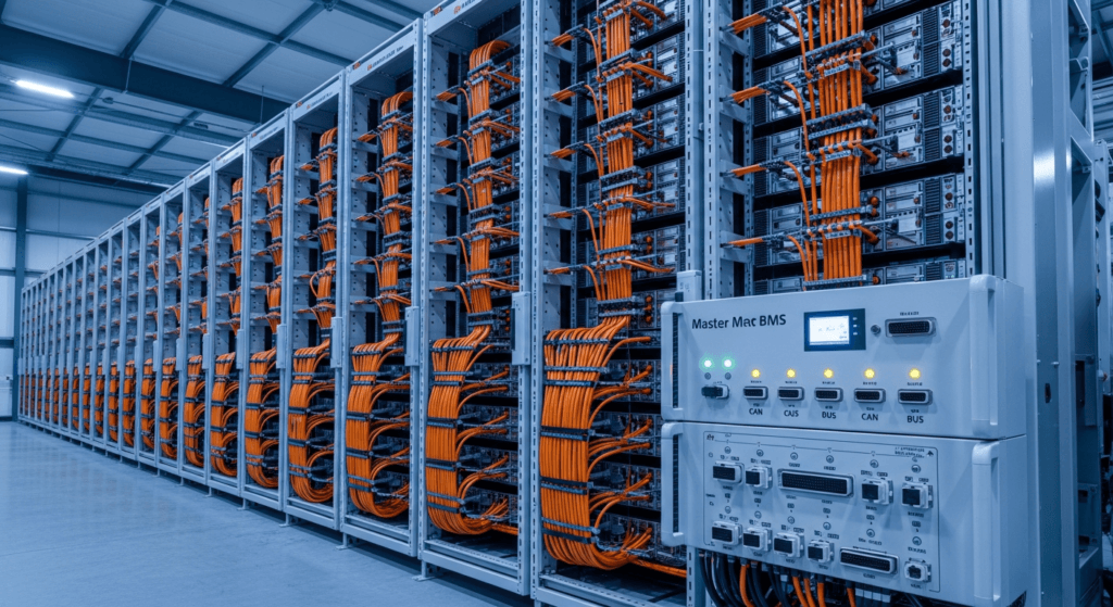
A modern solar system is a digital ecosystem. The BMS, MPPT, and inverter are in constant communication, typically over a CAN bus or similar protocol. This handshake is critical for managing cell health.
- Battery Management System (BMS): The BMS is the brain. It monitors the voltage of every individual cell (or parallel group). Its primary job is protection: preventing over-voltage, under-voltage, over-current, and over-temperature conditions. Crucially, it also performs cell balancing. Most standard BMS units use passive balancing, where small bleeder resistors are activated across the highest-voltage cells once they reach a certain threshold (e.g., 3.55V). This burns off excess energy as heat, allowing the lower-voltage cells to “catch up.” While effective, it’s slow and inefficient. Advanced systems use active balancing, which employs capacitors or inductors to shuttle energy from the highest-voltage cells to the lowest-voltage cells, actively redistributing charge.
- MPPT Charge Controller: The MPPT’s job is to maximize photon harvesting by converting the high-voltage, low-current DC from the solar array into the low-voltage, high-current DC needed to charge the battery. It receives commands from the BMS. When the BMS signals that a cell is approaching its high-voltage limit, the MPPT must throttle back the charging current, transitioning from the “Bulk” phase to the “Absorption” phase, and eventually to “Float.” An imbalanced bank forces this transition prematurely, wasting potential solar generation.
- Inverter: The inverter converts DC battery power to AC power for your loads. It also communicates with the BMS. If the BMS detects a cell dropping to its low-voltage cutoff, it will command the inverter to shut down to protect that cell, even if the overall bank voltage appears acceptable. This is why understanding solar inverter efficiency is tied directly to battery health; an efficient inverter can do more work with the available (and potentially limited) capacity.

The solution to imbalance lies in this synergy. A high-quality, configurable BMS with a sufficient balancing current (ideally >1A for larger banks), paired with a correctly programmed MPPT and inverter, forms the first line of defense.
Engineering Math & Sizing: The Root Cause of Imbalance
Chronic cell imbalance is often a symptom of a more fundamental design flaw: improper system sizing. An undersized battery bank is forced to operate at its voltage extremes and handle high C-rates (charge/discharge rates relative to capacity), which magnifies any minor inconsistencies between cells. Correctly sizing your battery is the most effective preventative measure.
The master formula for sizing a LiFePO4 battery bank for a solar system is:
Total Capacity (Wh) = (Daily Energy Consumption (Wh) × Days of Autonomy) / (Maximum Depth of Discharge (DoD) × System Efficiency)
Let’s break this down:
- Daily Energy Consumption (Wh): This is the most critical input. You must perform a detailed load analysis. Sum the wattage of every appliance and multiply by its daily hours of use. Be meticulous. A 15W router running 24/7 uses 360 Wh/day.
- Days of Autonomy: This is the number of consecutive cloudy days your system must endure. For mission-critical off-grid systems, 3 days is a common benchmark. For grid-tied systems with backup, 1 day may suffice.
- Maximum Depth of Discharge (DoD): For LiFePO4, this is a key advantage. You can regularly use 80-90% of the capacity (DoD = 0.8 to 0.9) without significant cycle life degradation. For maximum longevity (>6000 cycles), a 70% DoD is a conservative and wise choice.
- System Efficiency: This accounts for losses in the inverter (typically 5-10%), wiring (1-2%), and the battery’s own round-trip efficiency (for LiFePO4, this is excellent at ~95%). A conservative value of 0.85 (85%) is a safe starting point.
Example Calculation:
Daily Load: 5,000 Wh
Autonomy: 2 days
DoD: 0.8 (80%)
Efficiency: 0.85
Total Capacity = (5,000 Wh × 2) / (0.8 × 0.85) = 10,000 / 0.68 = 14,705 Wh or ~14.7 kWh.
Choosing a 10 kWh battery for this load profile would be a critical error, leading to deep discharges and high charge rates that would quickly induce cell imbalance. For a comprehensive look at pre-engineered solutions, our guide on the best off-grid solar kits of 2026 provides system-level sizing examples.
Master Comparison: 2026 Industry-Leading LiFePO4 Models
Selecting the right battery is a long-term investment. This table benchmarks five leading models based on metrics that directly influence ROI and system reliability. We analyze beyond marketing claims, focusing on Levelized Cost of Storage (LCOE) and verified cycle life data.
| Model | Capacity (kWh) | LCOE ($/kWh)* | Cycles @ 80% DoD | Max Discharge (A) | Warranty (Years) |
|---|---|---|---|---|---|
| SolarKiit SK48100 | 5.12 | $0.07 | 8000 | 100A (1C) | 15 |
| Battle Born BB10012 | 1.28 | $0.15 | 5000 | 100A (1C) | 10 |
| Victron Smart 25.6/200 | 5.12 | $0.18 | 5000 | 200A (2C) | 5 |
| EG4-LL-S 48V 100Ah | 5.12 | $0.09 | 7000 | 100A (1C) | 10 |
| Pylontech US5000 | 4.8 | $0.11 | 6000 | 90A (0.9C) | 10 |
*LCOE (Levelized Cost of Storage) calculated as: (Total Cost) / (Capacity × DoD × Cycle Life × Efficiency). Lower is better.
Regulatory & Safety Compliance: The Non-Negotiable Framework
In professional engineering, safety and compliance are not optional. When installing an energy storage system (ESS), you are legally and ethically bound to adhere to a strict set of codes and standards. These regulations are designed to prevent thermal runaway, electrical hazards, and structural failures.
NFPA 70: The National Electrical Code (NEC) 2026
The NEC is the foundational document for electrical safety in the United States. Article 706, “Energy Storage Systems,” is particularly relevant. Key mandates for 2026 include:
- Disconnecting Means: A readily accessible disconnect must be installed to isolate the ESS from all power sources. For a LiFePO4 system, this means disconnecting it from both the inverter/loads and the MPPT/solar array.
- Ventilation: While LiFePO4 batteries do not off-gas during normal operation like lead-acid batteries, NEC 706.31 requires that the space be ventilated to prevent the accumulation of hydrogen in the event of a catastrophic cell failure and electrolyte venting, however unlikely.
- Location and Spacing: The code specifies minimum clearances around the ESS for cooling and maintenance access. It also prohibits installation in certain locations, such as above habitable spaces in residential dwellings, unless specific fire-rated assemblies are used. You can find the full code on the NFPA 70: National Electrical Code website.
UL 9540 and UL 1973 Standards
These are not codes but are product safety standards that are often required by local jurisdictions and the NEC itself. A compliant system is a safe system.
- UL 1973 (Standard for Batteries for Use in Stationary Applications): This standard applies to the battery pack itself. It involves a battery of rigorous tests, including overcharge, short circuit, thermal abuse, and crush tests. A UL 1973 listing on your battery is a non-negotiable mark of quality and safety. It verifies the BMS will function as designed under fault conditions.
- UL 9540 (Standard for Energy Storage Systems and Equipment): This standard applies to the entire pre-packaged system (battery, inverter, controls). It ensures all components work together safely. A UL 9540 certified system has been tested as a complete unit, verifying the critical communication handshake between the BMS and the inverter. For more information on certification, UL Solutions (Solar Safety) is the definitive resource.
Fire Safety Protocols
LiFePO4 is the safest of all mainstream lithium-ion chemistries due to its stable olivine crystal structure. The P-O bond in the phosphate material is incredibly strong, making it highly resistant to thermal runaway. Unlike Nickel Manganese Cobalt (NMC) chemistries, it does not release oxygen when it decomposes, which is a primary accelerant in battery fires. However, safety is about layers. A proper installation includes a smoke or heat detector near the ESS and a Class ABC fire extinguisher nearby. The BMS’s thermal monitoring is the primary electronic fire prevention tool, designed to disconnect the battery long before a dangerous temperature is reached.
The Pillar FAQ: Your Engineering Questions Answered
1. What is the definitive, step-by-step engineering procedure for top-balancing a new LiFePO4 bank?
The definitive procedure involves individually charging each cell to its maximum voltage before connecting them in series. This ensures all cells start their operational life from an identical, 100% State of Charge (SOC) reference point, giving the BMS the best possible chance to maintain balance.
- Step 1: Isolate and Parallel. Disassemble the battery bank. Connect all cells in parallel (all positives together, all negatives together) using busbars. This creates a single, large cell where voltage is forced to be identical across all terminals.
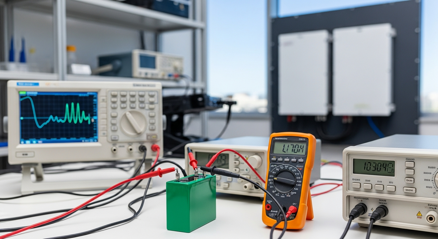
- Step 2: Calibrated Charging. Using a variable DC power supply, charge the parallel group at a low current (C/20 rate, e.g., 5A for a 100Ah bank). Set the voltage to the manufacturer’s recommended top-balance voltage, typically 3.65V.
- Step 3: Absorption Soak. Hold the voltage at 3.65V. The current will begin to taper off. The cells are considered fully balanced when the charge current drops to a very low level (e.g., <0.02C, or 2A for a 100Ah bank) and remains stable. This "soak" can take several hours and is the most critical step.
- Step 4: Rest and Verify. Disconnect the charger and let the cells rest for 1-2 hours. Their voltage will settle to around 3.40-3.45V. Use a high-precision multimeter to verify that the voltage across each cell is identical to within a few millivolts.
- Step 5: Reassemble and Torque. Reassemble the bank into its series configuration. Use a torque wrench to tighten all busbar connections to the manufacturer’s specification to ensure minimal resistance. This initial top-balance is the foundation for a long-lasting, high-performance system.
2. How does passive balancing differ from active balancing at the component and efficiency level?
Passive balancing dissipates energy as heat from high cells, while active balancing redistributes that energy to low cells. This fundamental difference has significant implications for efficiency and balancing speed, especially in high-cycle solar applications.
- Passive Balancing: This is the most common and cost-effective method. The BMS contains a small resistor and a switch (a MOSFET) for each cell. When a cell’s voltage exceeds a set threshold (e.g., 3.55V) during charging, the BMS closes the switch, shunting a small amount of current (typically 50-200mA) through the resistor. This “bleeds” the charge and generates heat. It is 0% efficient as the excess energy is wasted. It can only function during the charging phase and is very slow, making it unsuitable for correcting large imbalances or for systems with high charge rates.
- Active Balancing: This is a more advanced and efficient approach. It uses energy transfer elements to move charge from the most-charged cells to the least-charged cells.
- Capacitive/Inductive Balancers: These balancers use capacitors or inductors to store energy from a high cell and then release it into a low cell. They can operate at any time (charging, discharging, or at rest) and offer much higher balancing currents (1A to 10A+).
- DC-DC Converter Balancers: The most sophisticated type uses small DC-DC converters to transfer energy across the entire pack, from the highest cell directly to the lowest.
Active balancing is >85% efficient and can correct imbalances much faster, making it ideal for large battery banks and demanding applications. The ROI for an active balancer is realized through increased usable capacity and extended cycle life.
3. What is the financial ROI impact of a persistent 50mV cell imbalance over 5 years?
A persistent 50mV imbalance can reduce usable capacity by 10-20% and cut the battery’s cycle life in half, resulting in a negative ROI and premature replacement costs. The financial impact is not linear; it’s a compounding problem.
- Capacity Reduction: A 50mV (0.05V) difference means one cell hits the high-voltage cutoff (e.g., 3.65V) while others are only at 3.60V. Due to the steep voltage curve at the top of the charge, this can represent a 5-10% difference in SOC. The same occurs at the bottom. This effectively shrinks a 10kWh battery to an 8-9kWh battery, meaning you paid for capacity you cannot use.
- Cycle Life Degradation: The weak cell is consistently over-stressed. It is always the first to be fully charged and the first to be fully depleted. This “short cycling” of one cell causes accelerated degradation (Solid Electrolyte Interphase growth and loss of active material). While the other cells might be rated for 6,000 cycles, the weak cell may fail after just 2,000-3,000 cycles. Since the entire bank is only as good as its weakest cell, the entire multi-thousand-dollar investment is compromised.
- Quantified Loss (Example): On a $5,000, 10kWh battery bank designed for 6,000 cycles, a 50% reduction in life means you lose 3,000 cycles. This equates to a direct financial loss of $2,500 in asset value, not including the cost of replacement labor and the lost energy production during downtime.
4. What are the specific risks of “bottom balancing” versus “top balancing” in a solar application?
Top balancing is superior for solar as it protects against overcharging, the primary risk in systems with variable generation, while bottom balancing risks catastrophic cell failure. The choice depends on the application, and for solar, the choice is clear.
- Top Balancing: This method ensures all cells are full at the same time. The BMS has a clear, high-voltage cutoff reference for all cells. This is critical in a solar system where the charge source (the sun) is powerful and can rapidly increase voltage. By top balancing, you ensure no single cell can be overcharged, which is the most dangerous failure mode for LiFePO4 as it can lead to thermal events. The downside is a slight risk of the weakest cell being over-discharged if the BMS low-voltage cutoff is not configured conservatively, but this is a manageable risk.
- Bottom Balancing: This method ensures all cells are empty at the same time. It’s primarily used in Electric Vehicles (EVs) where knowing the exact “empty” point is critical for range calculation. In a solar system, it is dangerous. If you bottom balance, a stronger cell (with more capacity) will not be full when the weakest cell is. During a bright, sunny day, the MPPT will continue to pour energy into the bank. The weak cell will reach its 3.65V limit, but the stronger cell might only be at 3.55V. If the BMS passive balancer is too slow, the stronger cell will continue to accept charge, potentially pushing the weak cell into a dangerous over-voltage condition (>4.0V), risking permanent damage and venting.
5. How do ambient temperature variations across a large battery bank exacerbate cell imbalance?
Temperature variations directly impact a cell’s internal resistance and charge acceptance, causing cells in warmer spots to charge faster and age quicker, thus creating and worsening imbalance. This is a critical factor often overlooked in DIY installations.
- Physics of Temperature: The electrochemical reactions inside a battery are temperature-dependent. A warmer cell has lower internal resistance. During charging, this lower resistance means it will accept current more readily than a cooler cell. It will therefore reach the high-voltage cutoff point faster, even if it started at the same SOC as its cooler neighbors.
- The Vicious Cycle: This creates a feedback loop. The warmer cell charges faster, so its voltage rises. If the BMS uses passive balancing, the balancing resistor on that cell activates, generating even more heat. This localized heating accelerates the chemical degradation of that specific cell, permanently reducing its capacity and increasing its internal resistance over time, which ironically can make it run even hotter in subsequent cycles.
- Mitigation Strategy: The engineering solution is thermal management. For large battery banks, this means ensuring adequate, uniform airflow around every cell. A 2-3°C temperature delta across a bank is acceptable; a 5-10°C delta is a recipe for premature failure. This is why professional server-rack style batteries incorporate spacing and often forced-air cooling. When building a system, never stack prismatic cells tightly together without any air gaps. Proper thermal design is a cornerstone of knowing how to fix LiFePO4 battery cell imbalance in solar systems.
For any further inquiries or to discuss your specific system architecture, please feel free to contact our engineering team. We are dedicated to ensuring every solar installation is optimized for peak performance and longevity. The key to energy independence is not just generating power, but storing it with precision and reliability, which begins with understanding how to fix LiFePO4 battery cell imbalance in solar systems.
📥 Associated Resource:

El Kouriani Abde Civil Engineer & Founder of SolarKiit
El Kouriani Abde is a seasoned Civil Engineer and Project Manager with over 21 years of field experience. As the founder and publisher of SolarKiit.com, he leverages his deep technical background to simplify complex renewable energy concepts. His mission is to provide homeowners and professionals with accurate, engineering-grade guides to maximize their solar investments and achieve energy independence.