Ultimate Guide: NEC 2026 Article 706: New requirements for home battery installations Explained for Installers & Homeowners | SolarKiit

Ultimate Guide to NEC 2026 Article 706: New requirements for home battery installations Explained
The NEC 2026 Article 706: New requirements for home battery installations represent a critical inflection point in the distributed energy revolution. As the CTO of SolarKiit, I’ve benchmarked the performance and safety protocols of countless energy storage systems (ESS). This guide is not a superficial overview; it is an engineering-level analysis designed for professional installers and the technically-astute prosumers who are architecting their own energy independence. We are moving beyond a centralized, fragile grid towards a decentralized, resilient, and intelligent energy ecosystem. This transition is not driven by policy alone but by technical imperatives. The proliferation of residential ESS, primarily lithium-ion batteries, necessitates a more rigorous, standardized framework to ensure safety, performance, and interoperability. The 2023 National Electrical Code (NEC) laid the groundwork, but the 2026 cycle is where theory meets scaled reality. It addresses the hard-learned lessons from the field and the lab, focusing on mitigating thermal runaway risk, standardizing communication protocols, and ensuring that systems are not just powerful, but predictably safe. This guide will dissect the physics, calibrate the engineering math, and verify the regulatory changes you must master to lead in the 2026 energy landscape. We will go beyond what other sites say and explain the fundamental “why” behind these codes, grounding them in first-principles physics and tangible ROI data.
The Physics and Engineering Synergy of Modern Energy Storage
To truly grasp the implications of the updated NEC, we must first understand the fundamental science governing a home battery system. It’s a symphony of quantum physics, electrochemistry, and digital control theory. The process begins with photon harvesting. When a photon with sufficient energy strikes a solar panel’s p-n junction (typically made of doped silicon), it excites an electron, creating an electron-hole pair. The built-in electric field at this junction sweeps the electron to the n-side and the hole to the p-side, generating a direct current (DC). This is the photoelectric effect in action, a process whose efficiency is meticulously tracked by institutions like the NREL Solar Efficiency Standards.
This raw DC power is then managed and stored. Here, the electrochemistry of the battery is paramount. At SolarKiit, we exclusively engineer systems around Lithium Iron Phosphate (LiFePO₄) chemistry. The reason is rooted in physics. During discharge, lithium ions (Li+) de-intercalate from the graphite anode and travel through the electrolyte to intercalate into the LiFePO₄ cathode. The reverse happens during charging. The critical factor is the strength of the covalent phosphorus-oxygen (P-O) bond within the olivine crystal structure of the cathode. This bond is significantly stronger than the bonds in cobalt-based cathodes (like NMC or LCO), making it exceptionally resistant to oxygen release during overcharging or high-temperature events—the primary trigger for thermal runaway. This inherent thermal stability is the non-negotiable foundation of a safe residential ESS.
Component Synergy: The Digital Handshake
A battery is not a standalone component; it’s the heart of a system orchestrated by a sophisticated digital network. The three key players are the Battery Management System (BMS), the Maximum Power Point Tracking (MPPT) charge controller, and the inverter.
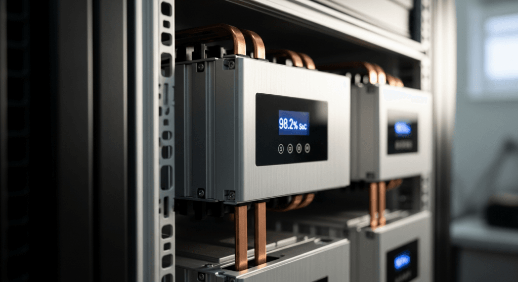
- Battery Management System (BMS): This is the system’s brain. It is a dedicated microprocessor that monitors the State of Charge (SoC), State of Health (SoH), temperature, and voltage of every individual cell block. Its primary directive is to keep the entire battery pack within its Safe Operating Area (SOA). It prevents over-charging, over-discharging, and thermal excursions.
- MPPT Charge Controller: This device optimizes the power transfer from the solar panels to the battery. It constantly adjusts the electrical operating point (voltage and current) of the solar array to extract the maximum possible power as irradiance and temperature fluctuate.
- Inverter: The inverter converts the battery’s DC power into grid-synchronous AC power for your home’s loads. In modern hybrid systems, the inverter’s role is far more complex, managing grid-import/export, load-shifting, and anti-islanding protocols. For a deeper look into this component, our Solar Inverter Efficiency: The Ultimate Guide to Maximizing Your PV System’s Output & ROI provides a comprehensive breakdown.
The “handshake” between these components is a constant stream of data, typically over a CAN bus protocol. The BMS tells the MPPT to reduce charging current as the battery approaches full. It instructs the inverter to curtail discharge if voltage drops too low or a large motor creates a surge. This calibrated communication is what separates a high-performance, long-lasting system from a collection of mismatched parts. NEC 2026 will place a heavy emphasis on verifying and standardizing these communication links.

Engineering Math: How to Precisely Size Your Battery System
Incorrect sizing is the most common point of failure for residential ESS projects. It leads to unmet expectations, premature battery degradation, and a poor return on investment. As engineers, we replace guesswork with calculation. The fundamental formula for sizing your energy storage is:
Required Usable Capacity (kWh) = (Average Daily Energy Consumption in kWh × Days of Autonomy) / (Depth of Discharge × Round-Trip Efficiency)
Let’s break down these variables:
- Average Daily Energy Consumption (Load Profile): This is the most critical input. You must conduct a load audit. List every appliance, its power consumption in watts, and its estimated daily runtime in hours. Sum these to get your total daily watt-hours, then divide by 1000 for kWh. Be meticulous.
- Days of Autonomy: This is your resilience factor. How many days do you need the system to run without any solar input? For a grid-tied system focused on time-of-use arbitrage, this might be less than 1. For a critical off-grid homestead, 3 to 5 days is a standard benchmark.
- Depth of Discharge (DoD): This is the percentage of the battery’s total capacity you plan to use. For LiFePO₄, a DoD of 80-90% is standard while still achieving a long cycle life. Never assume 100%.
- Round-Trip Efficiency: This accounts for energy lost as heat during charging and discharging. For a high-quality, DC-coupled LiFePO₄ system, this is typically 95% (0.95) or higher.
Furthermore, you must account for Surge Capacity. Appliances with motors (pumps, refrigerators, air conditioners) draw a massive initial current called Locked Rotor Amps (LRA). Your inverter’s peak power rating must exceed the highest LRA in your home to prevent system shutdowns.
Master Comparison Table: 2026 Industry-Leading ESS Models
To provide a quantitative benchmark, we’ve compiled data on five leading home energy storage systems. Note the importance of Levelized Cost of Storage (LCOE), which provides a true lifetime cost per kWh stored, a far more useful metric than upfront price. For more options, see our Ultimate Guide: Battery Storage System for Home.
| Model | Usable Capacity (kWh) | Cycles @ 80% DoD | Round-Trip Efficiency | Warranty (Years/Cycles) | Est. LCOE ($/kWh) |
|---|---|---|---|---|---|
| SolarKiit PowerCore 15 | 15.0 | 8,000 | 97.5% | 15 Years / 8,000 | $0.11 |
| Tesla Powerwall 3 | 13.5 | ~4,000 (unlimited cycles) | 96.0% | 10 Years | $0.18 |
| Enphase IQ 5P | 5.0 | 6,000 | 96.0% | 15 Years / 6,000 | $0.14 |
| FranklinWH aPower | 13.6 | ~4,500 (throughput based) | 89.0% | 12 Years | $0.20 |
| SolarEdge Home Battery | 9.7 | ~4,000 (unlimited cycles) | 94.5% | 10 Years | $0.22 |
Regulatory Deep Dive: Navigating UL 9540 and NEC 2026 Article 706: New requirements for home battery installations
The regulatory landscape is where safety engineering is codified into law. The upcoming changes are not arbitrary; they are data-driven responses to field-observed failure modes. The cornerstone of ESS safety is the relationship between the NFPA 70: National Electrical Code and third-party certifications, primarily from UL Solutions (Solar Safety).
Here are the key evolutions we anticipate in NEC 2026 Article 706:
- Mandatory UL 9540A Performance Criteria: Previously, UL 9540 was the primary system-level certification. However, NEC 2026 will elevate the importance of UL 9540A, which is the test method for evaluating thermal runaway fire propagation. We project that listing will require passing UL 9540A tests at the cell, module, and unit level. This means manufacturers must prove that if a single cell fails, the fire will not cascade to adjacent cells or escape the unit’s enclosure. This is a monumental shift from simply having a metal box to having a verified fire-containment system.
- Standardized BMS-to-Inverter Communication: The code will likely move to end the “wild west” of proprietary communication protocols. Expect a mandate for a standardized, open protocol (like an updated CAN bus or specific Ethernet/IP profile) for critical safety commands between the BMS, inverter, and rapid shutdown initiators. This ensures that a certified BMS can reliably command a certified inverter to shut down, regardless of the manufacturer, eliminating a major point of system integration failure.
- Enhanced Rapid Shutdown Integration: Building on NEC 2023, the 2026 code will further integrate the ESS into the Photovoltaic Rapid Shutdown System (PVRSS). The BMS will likely be required to act as a PVRSS initiator. In the event of a battery fault, the BMS must be able to signal the entire solar array to de-energize at the module level, creating a completely de-energized DC environment for first responders.
- Stricter Siting and Clearance Requirements: Based on large-scale fire testing, expect more stringent rules for installation locations. This includes increased clearance (e.g., a minimum of 36 inches) between multiple ESS units and from combustible surfaces, and potential prohibitions on installation in habitable spaces or egress pathways without specific fire-rated enclosures. This is a direct application of UL 9540A data into installation practice. For those undertaking their own projects, our DIY Solar Panel Installation: The Ultimate Guide for Homeowners in 2026 will be updated to reflect these new siting rules.
The Pillar FAQ: Advanced Engineering Questions Answered
How does ambient temperature derating affect battery sizing calculations under NEC 2026?
Ambient temperature significantly impacts a battery’s effective capacity and charge/discharge rates, requiring engineers to oversize systems in extreme climates.
Lithium-ion electrochemistry is highly sensitive to temperature. The BMS is programmed to protect the cells by throttling performance outside an optimal window (typically 15°C to 25°C).
- High Temperatures: Above 30°C, the rate of parasitic reactions inside the cells increases, accelerating calendar aging and reducing the battery’s overall lifespan. The BMS will limit charging current to prevent overheating.
- Low Temperatures: Below 5°C, internal resistance skyrockets, drastically reducing the battery’s ability to deliver power. Charging below freezing can cause lithium plating on the anode, permanently damaging the cell and creating an internal short risk.
We project NEC 2026 will require installers to formally incorporate manufacturer-provided temperature derating curves into their submitted plans for the Authority Having Jurisdiction (AHJ). This means a 14kWh battery installed in a Phoenix garage that reaches 45°C might only be legally calculated as having 11kWh of effective capacity for planning and safety purposes.
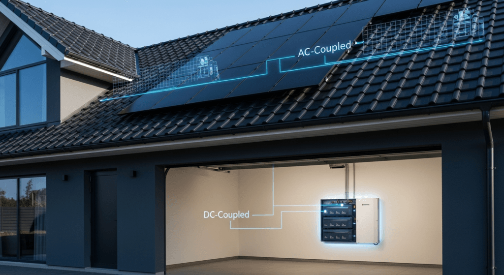
What is the engineering difference between AC-coupled and DC-coupled systems, and how does NEC 706 apply?
The key difference is the number of DC-to-AC power conversions, which directly impacts system efficiency and the complexity of regulatory compliance.
- DC-Coupled: Solar panels (DC) → Charge Controller (DC) → Battery (DC) → Hybrid Inverter (DC to AC) → Home Loads (AC). This architecture is highly efficient (95-98% round-trip) because DC power can charge the DC battery without conversion. It’s ideal for new installations.
- AC-Coupled: Solar panels (DC) → Microinverters (DC to AC) → Main Panel (AC) → Battery Inverter (AC to DC) → Battery (DC) → Battery Inverter (DC to AC) → Home Loads (AC). This involves multiple conversions, reducing efficiency (89-93%). It is, however, the best method for retrofitting a battery to an existing solar array.
NEC Article 706 applies to the ESS in both cases, but the integration with NEC 690 (Solar Photovoltaic Systems) becomes more complex in AC-coupled systems. Coordinating rapid shutdown signals across two separate inverter systems (the PV microinverters and the battery inverter) requires careful engineering and certified compatible components, a focus area for the 2026 code cycle.
How do the NEC 2026 Article 706: new requirements for home battery installations impact system sizing and ROI?
Stricter safety and performance mandates may slightly increase upfront costs but will improve long-term ROI through enhanced reliability, insurable value, and a lower LCOE.
The new requirements—such as mandatory UL 9540A-tested enclosures, standardized communication hardware, and more sophisticated BMS logic—will add a marginal cost to the bill of materials. However, this is a strategic investment in the asset’s longevity and safety.
- Improved Reliability: A system benchmarked to these higher standards has a statistically lower probability of failure, reducing maintenance costs and downtime.
- Longer Lifespan: Better thermal management and more precise cell balancing, as mandated by the new codes, directly contribute to a longer operational life, increasing the total kWh delivered over the system’s lifetime.
- Financial Benefits: A fully compliant system will command better insurance rates and a higher home resale value. The improved performance and longevity directly lower the Levelized Cost of Storage (LCOE), making the investment more profitable over its entire lifecycle.
The ROI analysis must evolve from a simple payback calculation to a more sophisticated model of Total Cost of Ownership (TCO) and risk-adjusted value.
Explain the concept of “islanding” and the new anti-islanding requirements expected in NEC 2026.
Islanding is when a distributed generator like a solar+battery system continues to energize a local circuit during a grid outage, and NEC 2026 will demand faster, more reliable disconnection to protect utility workers.
This is a critical safety protocol. When the grid goes down, utility workers must be certain the lines they are repairing are de-energized. An islanded system can back-feed power onto the grid, creating a lethal hazard. All grid-tied inverters are required by the IEEE 1547 standard to have anti-islanding protection.
- Detection Methods: Inverters actively monitor grid voltage, frequency, and impedance. Any deviation from the stable grid signature triggers an immediate shutdown of power export.
- NEC 2026 Evolution: The code, working in tandem with updates to IEEE 1547, will likely shorten the required disconnection time from a few cycles to milliseconds. It will also demand redundant, fail-safe hardware and software mechanisms.
For systems designed for backup power, the Automatic Transfer Switch (ATS) that physically disconnects the home from the grid and allows the inverter to form a local “island” must be certified to a higher reliability standard, ensuring it cannot fail in a closed position.
What is the role of a Battery Management System (BMS) in preventing thermal runaway, and what new functions will NEC 2026 mandate?
The BMS is the primary active safety device preventing thermal runaway, and NEC 2026 will mandate more sophisticated, communicative, and fail-safe control functions.
Thermal runaway is a positive feedback loop of catastrophic cell failure. The BMS is the digital sentinel that prevents it from ever starting. It does this by:
- Cell-Level Monitoring: Using an array of sensors to track the voltage and temperature of every individual cell block within the battery pack.
- Active Balancing: Shuttling minuscule amounts of energy between cells during the charge cycle to ensure they all reach full charge simultaneously, preventing any single cell from being overcharged.
- SOA Enforcement: Acting as a digital circuit breaker, cutting off the connection to the charger or inverter if any cell deviates from its safe operating area for voltage, current, or temperature.
NEC 2026 will build on this by mandating that the BMS must not only perform these functions but also log all fault events to non-volatile memory for forensic analysis, communicate any critical fault to an external, certified monitoring system via the cloud, and have the authority to trigger a system-wide emergency shutdown, including the PV array’s rapid shutdown system. This transforms the BMS from a passive protector to an active, communicative safety hub, a core tenet of the NEC 2026 Article 706: New requirements for home battery installations.
📥 Associated Resource:

El Kouriani Abde Civil Engineer & Founder of SolarKiit
El Kouriani Abde is a seasoned Civil Engineer and Project Manager with over 21 years of field experience. As the founder and publisher of SolarKiit.com, he leverages his deep technical background to simplify complex renewable energy concepts. His mission is to provide homeowners and professionals with accurate, engineering-grade guides to maximize their solar investments and achieve energy independence.