portable battery power station: The Ultimate Guide to Off-Grid Power & Home Backup
Strategic Overview: The 2026 Portable Power Paradigm
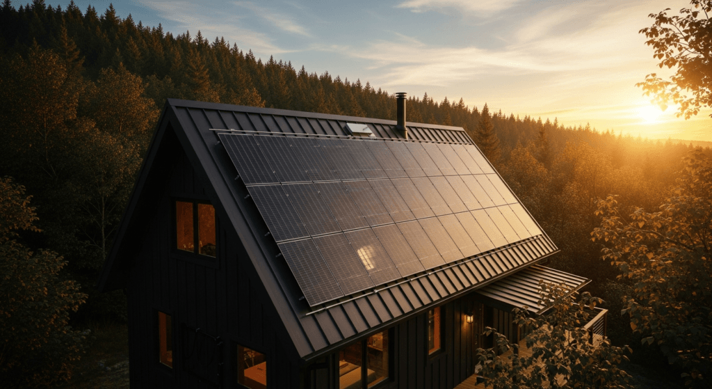
By 2026, the portable battery power station market has fundamentally evolved beyond a niche for campers and emergency preppers. It now represents a critical nexus of consumer electronics, renewable energy, and grid resilience. This maturation is driven by three primary vectors: accelerated battery technology transfer from the electric vehicle (EV) sector, increasing grid instability due to climate events and aging infrastructure, and the democratization of solar power through highly efficient, plug-and-play photovoltaic (PV) systems.
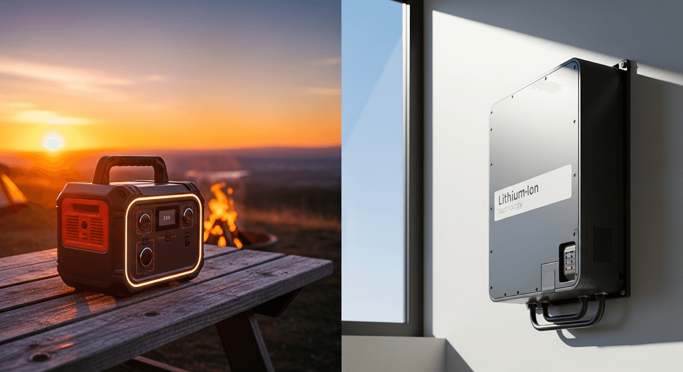
The dominant battery chemistry has decisively shifted to Lithium Iron Phosphate (LiFePO4), prized for its superior thermal stability, extended cycle life (often exceeding 3,500 cycles), and improved safety profile over older Lithium Nickel Manganese Cobalt (NMC) chemistries. This transition has enabled manufacturers to offer warranties of up to 10 years, positioning these devices not as disposable gadgets, but as long-term home energy assets.
Furthermore, the concept of a “portable” station has bifurcated. We now see ultra-compact units under 1 kWh for personal electronics and massive, modular systems exceeding 10 kWh that rival fixed home battery installations like the Tesla Powerwall. These larger systems, often equipped with 30A or 50A outlets, can integrate directly into a home’s electrical panel via a transfer switch, offering a scalable and transportable alternative to permanent backup solutions. The 2026 landscape is defined by this modularity, enhanced safety, and deep integration into the smart home ecosystem.
Deep Technical Analysis: From Photon to Appliance
Understanding the engineering principles behind a portable power station is critical for optimizing its performance. The process involves a multi-stage energy conversion, with efficiency losses at each step. A holistic view of this “photon-to-plug” journey reveals the true capability of a system beyond its marketing specifications.
The Physics of Energy Conversion and Storage
The entire operation begins with the photovoltaic effect. When photons from sunlight strike a solar panel’s semiconductor material (typically monocrystalline silicon), they excite electrons, creating a direct current (DC). The voltage and amperage of this DC output are highly variable, dictated by the solar irradiance (W/m²) and the panel’s temperature. This raw, unstable DC power is unsuitable for directly charging a battery.
This is where the Maximum Power Point Tracking (MPPT) charge controller becomes essential. An MPPT is a sophisticated DC-to-DC converter. It continuously analyzes the solar panel’s I-V (current-voltage) curve to find the “knee” – the optimal voltage and current combination that yields the maximum power output (P = V × I). By constantly adjusting the load, the MPPT ensures the panel operates at its peak efficiency, often boosting energy harvest by up to 30% compared to older PWM controllers, especially in cold or partially shaded conditions.
The regulated DC output from the MPPT then charges the internal battery pack. The Battery Management System (BMS) acts as the brain of this process. It monitors the voltage, current, and temperature of individual cell groups, ensuring they remain within safe operating parameters. The BMS prevents overcharging, over-discharging, short circuits, and thermal runaway, which is paramount for the longevity and safety of the LiFePO4 cells.
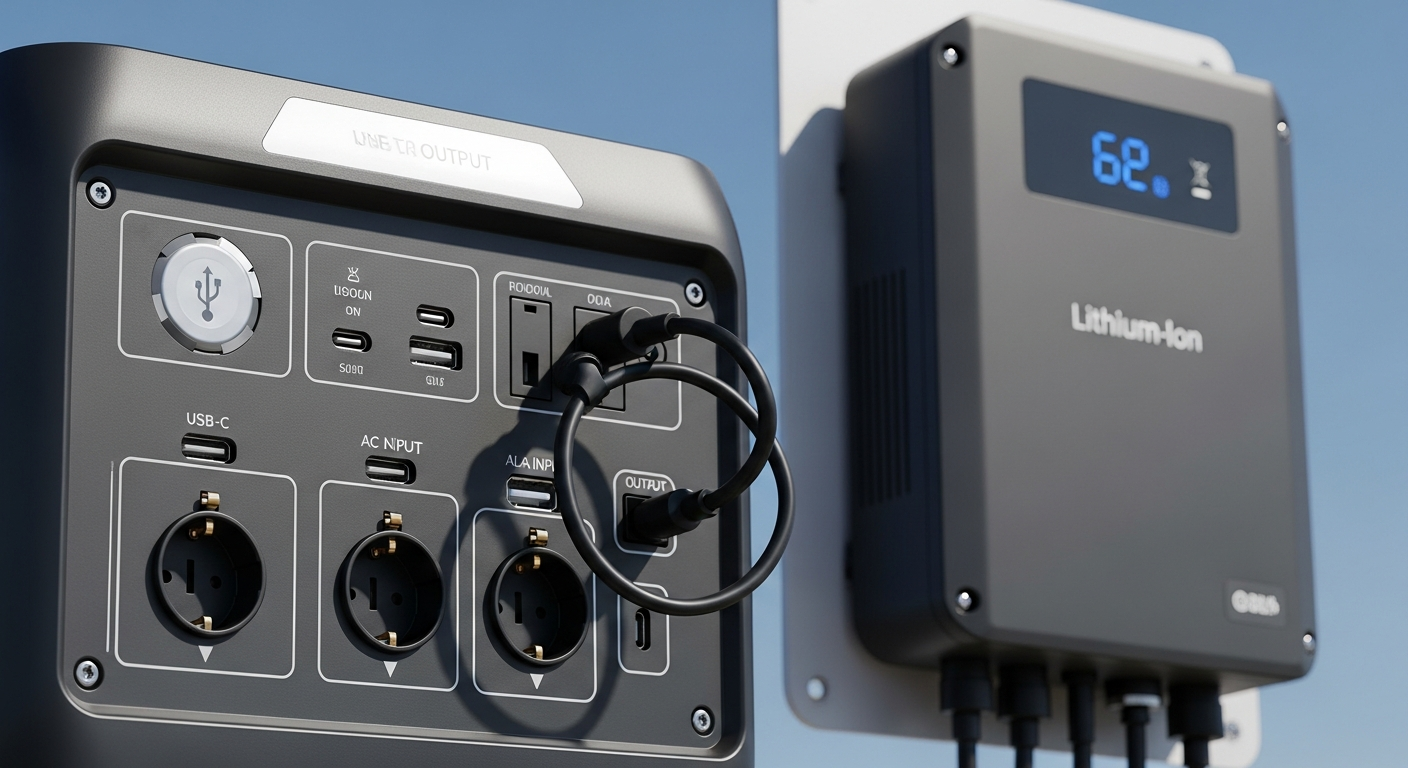
Finally, to power common household appliances, the stored DC energy must be converted to Alternating Current (AC). This is the role of the inverter. In 2026, the industry standard is the Pure Sine Wave inverter, which produces a clean, smooth electrical waveform identical to grid power. This is crucial for sensitive electronics like laptops, medical devices (CPAP), and variable-speed motors, which can be damaged or malfunction with a lower-quality Modified Sine Wave inverter.
Efficiency Benchmarks and System Losses
Total system efficiency is a product of the efficiencies of its components. In 2026, a high-end system exhibits the following benchmarks:
- Photovoltaic (PV) Panel Efficiency: Monocrystalline TOPCon (Tunnel Oxide Passivated Contact) or HJT (Heterojunction) cells now achieve 23-25% conversion efficiency in commercial panels.
- MPPT Controller Efficiency: Modern controllers consistently operate at over 99% efficiency, meaning negligible power is lost during DC-DC conversion.
- Battery Round-Trip Efficiency: LiFePO4 chemistry offers a round-trip efficiency of approximately 92-95%. This means for every 100 Wh of energy put into the battery, 92-95 Wh can be retrieved.
- Inverter Efficiency: Pure Sine Wave inverters typically operate at 90-94% efficiency under optimal load. Efficiency drops at very low or very high loads relative to the inverter’s capacity.
Calculating the total “photon-to-plug” efficiency: 0.24 (PV) × 0.99 (MPPT) × 0.95 (Battery) × 0.92 (Inverter) ≈ 0.207. This means that under ideal conditions, only about 20.7% of the solar energy hitting the panel is delivered as usable AC power to your appliance. Understanding this cascade of losses is vital for realistic expectations and proper system sizing.
Load Calculation and Sizing Strategies
Properly sizing a power station requires a detailed analysis of your energy needs. The two primary metrics are battery capacity (in Watt-hours, Wh, or kilowatt-hours, kWh) and inverter output (in Watts, W).
1. Sizing Battery Capacity (Energy): First, list all devices you intend to power. For each, find its power consumption in Watts and estimate the number of hours it will run. The required energy is calculated as: Energy (Wh) = Power (W) × Time (h). Sum the Wh for all devices to get your total daily energy requirement. A crucial engineering practice is to add a safety margin of at least 20% to account for system inefficiencies and unexpected usage.
Example: A 100W refrigerator running for 8 hours/day (33% duty cycle) and a 50W fan running for 10 hours/day requires (100W * 8h) + (50W * 10h) = 800Wh + 500Wh = 1300Wh. Applying a 20% margin: 1300 * 1.2 = 1560Wh. You would need a station with at least a 1.6 kWh capacity.
2. Sizing the Inverter (Power): The inverter must handle the combined power of all devices running simultaneously. This is the continuous load. However, a more critical specification is the surge or peak load. Motors in appliances like refrigerators and power tools draw a massive, momentary surge of power to start up, often 2-3 times their running wattage. Your station’s inverter must have a surge rating that exceeds the highest potential surge from your devices to avoid a system shutdown.
Engineering Specifications & Innovations in 2026
The competitive landscape is driving rapid innovation, with leading brands differentiating through proprietary technologies and advanced material science. These are not just marketing terms; they represent tangible engineering advancements that define a product’s performance envelope.
EcoFlow’s X-Stream & Modular Ecosystem: EcoFlow continues to lead in charging technology. Their proprietary X-Stream charging bypasses the need for a bulky external power brick, allowing direct AC input for ultra-fast charging. The 2026 Delta Pro series can achieve an 80% charge in under 50 minutes from a standard wall outlet. Their ecosystem is built on modularity; a base Delta Pro 2 unit (approx. 4 kWh) can be expanded with smart extra batteries, daisy-chaining up to 25 kWh of capacity, rivaling dedicated home storage solutions while retaining portability.
Bluetti’s Sodium-Ion and Fusion Panels: While LiFePO4 remains the standard, Bluetti has pioneered the commercial introduction of Sodium-ion (Na-ion) batteries in select models. Na-ion cells offer superior performance in extreme cold, are less resource-constrained than lithium, and promise even greater safety. Bluetti’s AC700 series also showcases “Fusion Panels,” which integrate a high-amperage AC output by linking two units in parallel, effectively doubling the continuous and surge power output for demanding loads like welders or whole-home backup.
Victron Energy’s Component-Based Architecture: Victron targets the pro-sumer and professional market with a component-based approach. Instead of an all-in-one unit, a Victron system (e.g., a “Nomad Kit”) is built from discrete, over-engineered components: a MultiPlus inverter/charger, a SmartSolar MPPT, and a Cerbo GX for system control. This allows for unparalleled customization, serviceability, and performance monitoring through their Victron Remote Management (VRM) portal, which provides deep analytics on every aspect of the system’s operation.
Tesla’s Vertical Integration (Hypothetical “CyberPower”): While not yet released, industry analysis points to a forthcoming Tesla portable power station. Leveraging their 4680 structural battery pack technology and advanced BMS algorithms from their automotive division, a hypothetical “CyberPower” unit would offer unmatched energy density and intelligent power management. Integration with the Tesla app ecosystem would allow seamless control and monitoring alongside a vehicle and Powerwall, creating a unified energy environment.
Emerging Cell and PV Materials: Beyond brand-specific tech, materials science is pushing boundaries. Perovskite solar cells, while still facing longevity challenges, are being integrated into flexible, lightweight PV blankets. These cells offer superior low-light performance, making them ideal for charging on overcast days. Solid-state batteries are also on the horizon, promising a step-change in energy density and safety, though their integration into mainstream portable power stations is likely still a few years beyond 2026.
Technical Comparison of 2026 Leading Models
| Model (Hypothetical 2026) | Battery Capacity (kWh) | Chemistry / Cycles | Continuous / Surge Output (W) | Max Solar Input (W) | Key Engineering Feature |
|---|---|---|---|---|---|
| EcoFlow Delta Pro 2 | 4.1 kWh (Expandable to 25 kWh) | LiFePO4 / 4000+ | 4000W / 7500W | 2400W | X-Stream 3.6kW AC Fast Charge; Modular Expansion |
| Bluetti AC700S | 3.2 kWh (Expandable to 12.8 kWh) | Sodium-Ion / 3500+ | 3300W / 6000W | 2000W | Superior cold-weather performance; Fusion Panel Parallel Capability |
| Victron “Nomad 3000” Kit | 3.0 kWh (Customizable) | LiFePO4 / 5000+ | 3000W / 6000W | 145V / 70A MPPT (~4000W) | Component-based architecture; VRM remote analytics |
| Anker SOLIX F4200 | 4.2 kWh (Expandable to 21 kWh) | LiFePO4 / 3500+ | 3800W / 7000W | 2200W | GaNPrime Inverter Technology for higher efficiency and lower heat |
| Tesla “CyberPower 3” | 3.5 kWh | 4680-Cell Li-Ion / 3000+ | 3500W / 6500W | 1800W | Unmatched energy density; Deep integration with Tesla vehicle/app |
Safety, Standards, and System Hardening
As power stations become more powerful, adherence to electrical codes and safety standards is non-negotiable. A robust system is not just about capacity; it’s about safe, reliable operation under all conditions. Engineers and informed consumers must prioritize systems that meet stringent third-party certifications.
NEC Compliance and Home Integration: When a portable power station is used for home backup, it falls under the purview of the National Electrical Code (NEC). Connecting the station to your home’s breaker panel requires a transfer switch. This device is critical as it prevents “back-feeding” the grid, a dangerous situation that can electrocute utility workers. NEC Article 705 governs such interconnections. A manual transfer switch is a cost-effective solution, while an automatic transfer switch (ATS) provides seamless power transition during an outage.
Ingress Protection (IP) Ratings: The IP rating defines a device’s resistance to solids and liquids. For a unit intended for outdoor or field use, a rating of IP65 is the minimum acceptable standard. The ‘6’ indicates it is dust-tight, while the ‘5’ signifies protection against low-pressure water jets from any direction. For more extreme environments, an IP67 rating ensures the unit can withstand temporary immersion in water up to 1 meter, providing a much higher degree of system hardening against the elements.
Fire Safety and Thermal Management: The choice of LiFePO4 chemistry is the first line of defense against fire. Its phosphate-based cathode is structurally and chemically more stable than the cobalt-oxide cathodes in NMC batteries, with a thermal runaway threshold exceeding 270°C, compared to ~210°C for NMC. The second line of defense is the BMS, which must have redundant temperature sensors and algorithms to throttle charging/discharging or shut down the system entirely if cell temperatures exceed safe limits. Look for certifications like UL 9540 for Energy Storage Systems and Equipment.
Pre-Installation Operational Checklist
- Verify PV Voltage Compatibility: Check the solar panel’s “Open-Circuit Voltage” (Voc) specification. This value must be below the maximum input voltage rating of the power station’s MPPT controller to prevent permanent damage.
- Calculate Voltage Drop: For long cable runs between the solar panel and the power station, use an online voltage drop calculator. Ensure the wire gauge (AWG) is thick enough to keep voltage drop below 3% to maximize power transfer.
- Confirm Connector Polarity: Before plugging in solar panels, use a multimeter to verify the polarity of the MC4 or Anderson connectors. Reversing polarity can damage the charge controller.
- Assess PV Orientation and Azimuth: For stationary setups, use a solar pathfinder app to determine the optimal tilt angle and orientation (true south in the Northern Hemisphere) to maximize daily energy yield.
- Grounding Verification: Ensure the power station is properly grounded according to the manufacturer’s instructions, especially when connecting to a home’s electrical system or powering heavy machinery.
- Firmware Update: Before first use, connect the unit to Wi-Fi (if applicable) and check for firmware updates. These updates often include critical improvements to charging algorithms and BMS safety protocols.
- Initial Capacity Calibration: Perform a full charge-discharge-charge cycle (100% -> ~10% -> 100%) to calibrate the BMS and ensure accurate state-of-charge reporting.
–
Advanced Engineering FAQ
What is the technical significance of a battery’s C-rating in a power station?
The C-rating quantifies the rate at which a battery can be charged or discharged relative to its capacity. A 1C rating on a 2000Wh battery means it can theoretically discharge its entire capacity in 1 hour, delivering 2000W continuously. A 0.5C rating means it can deliver 1000W for 2 hours. In power stations, a higher discharge C-rating is crucial for the inverter to meet high surge demands, while a high charge C-rating enables rapid charging technologies like EcoFlow’s X-Stream. LiFePO4 batteries typically have excellent C-ratings, but pushing them to their maximum C-rate consistently can reduce their overall cycle life.
How does inverter wave type (Pure Sine vs. Modified Sine) impact sensitive electronics?
A Pure Sine Wave inverter produces a smooth, periodic AC waveform identical to grid power. A Modified Sine Wave inverter approximates this with a blocky, stepped waveform. This “dirty” power can cause issues in sensitive electronics. AC motors may run hotter and less efficiently, audio equipment may have a persistent hum, and some medical devices or appliance control boards may not function at all. The sharp voltage steps of a modified wave can stress power supplies, leading to premature failure. For any modern electronic device, a Pure Sine Wave inverter is a mandatory engineering requirement.
Can I chain multiple solar panels in series vs. parallel, and what are the implications for the MPPT controller?
Yes, and the choice has significant implications. Connecting panels in series (positive to negative) adds their voltages while keeping the current the same. This is advantageous for long cable runs as higher voltage reduces resistive current loss (P_loss = I²R). However, the total series voltage (Voc) must not exceed the MPPT’s max voltage limit. Connecting in parallel (positive to positive, negative to negative) adds the currents while keeping the voltage the same. This is more tolerant to partial shading, as a shaded panel in a series string can cripple the output of the entire string. The optimal configuration depends on the MPPT’s voltage/amperage window and the environmental conditions.
Explain the concept of “pass-through charging” and its effect on battery longevity.
Pass-through charging allows a power station to power connected AC/DC devices while it is simultaneously being charged. In a well-engineered system, the incoming power is intelligently routed directly to the inverter and DC outputs if the load is less than the input power. The excess power is then used to charge the battery. This is superior to a naive implementation where the battery is constantly being charged and discharged simultaneously (a micro-cycle), which would degrade its health. High-quality pass-through functionality essentially turns the unit into an Uninterruptible Power Supply (UPS) and, when properly managed by the BMS, has a minimal impact on battery longevity.
What role does the Battery Management System (BMS) play beyond basic safety?
Beyond preventing catastrophic failure, an advanced BMS performs several sophisticated functions. It executes cell balancing, ensuring all cell groups within the pack maintain an equal state of charge, which maximizes usable capacity and extends cycle life. It performs “coulomb counting” and voltage curve analysis to provide an accurate State of Charge (SoC) percentage to the user. Furthermore, it manages the battery’s thermal state, throttling charge/discharge rates based on ambient and internal temperatures to optimize both performance and long-term health. In smart, connected units, the BMS also logs data for diagnostics and predictive maintenance alerts.
📥 Associated Resource:

El Kouriani Abde Civil Engineer & Founder of SolarKiit
El Kouriani Abde is a seasoned Civil Engineer and Project Manager with over 21 years of field experience. As the founder and publisher of SolarKiit.com, he leverages his deep technical background to simplify complex renewable energy concepts. His mission is to provide homeowners and professionals with accurate, engineering-grade guides to maximize their solar investments and achieve energy independence.