portable power station: The Ultimate Guide to Off-Grid & Emergency Power
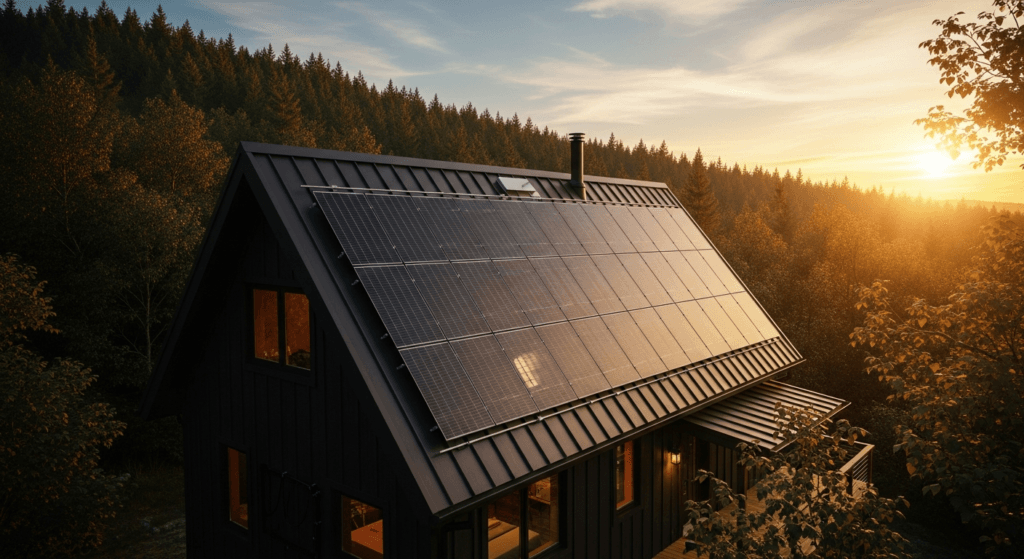
The paradigm of energy consumption is undergoing a seismic shift. By 2026, the concept of energy independence is no longer a fringe ideal but a mainstream necessity. Driven by an aging and increasingly fragile grid, the escalating frequency of extreme weather events, and a societal move towards mobile, flexible lifestyles, the portable power station has evolved from a camper’s convenience into a cornerstone of residential and commercial resilience.
In this new landscape, these devices are not mere batteries; they are sophisticated, self-contained microgrids. The market is witnessing a convergence of technologies from the electric vehicle (EV) sector, residential solar storage, and consumer electronics. This fusion has catalyzed rapid advancements in battery energy density, inverter efficiency, and intelligent power management, making 2026-era systems more powerful, safer, and more integrated than ever before.
This guide moves beyond surface-level reviews to provide a deep engineering analysis of the systems defining off-grid and emergency power. We will dissect the core components, from the photovoltaic cells capturing photons to the pure sine wave inverter powering your most sensitive electronics. Our focus is on empowering you with the technical knowledge to size, select, and safely operate a portable power station that meets the rigorous demands of the modern world.
Deep Technical Analysis: From Photon to Power
Understanding a portable power station requires a granular look at its core subsystems: the energy generation source (photovoltaics), the charge controller, the energy storage medium (battery), and the power delivery system (inverter). The overall system efficiency is a product of the efficiencies of these individual components.
The Physics of Energy Conversion and Storage
The process begins with solar panels. By 2026, the dominant technology in high-performance portable panels is Tunnel Oxide Passivated Contact (TOPCon) or Heterojunction (HJT) monocrystalline silicon. When photons with sufficient energy strike the N-type silicon layer, they create electron-hole pairs. The internal electric field at the P-N junction separates these charges, forcing electrons to flow through an external circuit—this is the photovoltaic effect, generating Direct Current (DC).
This raw DC power is fed into a Maximum Power Point Tracking (MPPT) charge controller. An MPPT is a high-frequency DC-to-DC converter. It continuously samples the solar panel’s voltage (V) and current (I) to find the “maximum power point” on its I-V curve, which varies with solar irradiance and temperature. By adjusting its input impedance, the MPPT ensures the panel operates at this optimal voltage, harvesting up to 30% more energy than older Pulse Width Modulation (PWM) controllers, especially in suboptimal light conditions.
The regulated DC power from the MPPT then charges the battery. The standard is now Lithium Iron Phosphate (LiFePO4). Charging is an electrochemical process where lithium ions are extracted from the cathode (LiFePO4) and intercalated into the graphite anode. This process stores electrical energy as chemical potential energy. The Battery Management System (BMS) is the critical brain, monitoring cell voltage, temperature, and current to prevent overcharging, over-discharging, and thermal runaway.
Finally, to power common household devices, the stored DC energy must be converted to Alternating Current (AC). This is the job of the inverter. A pure sine wave inverter uses sophisticated high-frequency switching and filtering to generate a smooth, clean AC waveform identical to grid power. This is non-negotiable for sensitive electronics like laptops, medical equipment (CPAP), and variable-speed motors, which can be damaged by the “blocky” output of a modified sine wave inverter.
Efficiency Benchmarks and System Losses in 2026
Every conversion step incurs an energy loss, typically as heat. A “photon-to-plug” efficiency calculation reveals the true performance:
- Photovoltaic (PV) Efficiency: Premium portable panels using TOPCon cells achieve 24-26% efficiency. This means for every 1000W of solar energy striking the panel, 240-260W of DC electricity is generated.
- MPPT Controller Efficiency: Modern MPPTs boast peak efficiencies of 98-99.5%. This is a minimal loss point in the system.
- Battery Round-Trip Efficiency: LiFePO4 chemistry offers a superior round-trip efficiency of 92-95%. For every 100Wh of energy put into the battery, you can retrieve 92-95Wh.
- Inverter Efficiency: High-quality pure sine wave inverters operate at 90-94% efficiency under optimal load. Efficiency drops at very low or very high loads relative to the inverter’s rating.
A typical system calculation: 1000W solar input * 25% (PV) * 99% (MPPT) * 94% (Battery) * 92% (Inverter) = ~213W of usable AC power. This highlights the compounding nature of losses and the importance of high-efficiency components.
Load Calculation and Sizing Strategy
Properly sizing a power station is the most critical step. Under-sizing leads to system failure, while over-sizing results in unnecessary cost and weight.
Step 1: Calculate Daily Energy Consumption (Watt-hours). List all devices you intend to power. For each, find its power consumption in Watts (W) and estimate its daily run time in hours (h).
Energy (Wh) = Power (W) * Time (h)
Sum the Watt-hours for all devices to get your total daily energy requirement.
Step 2: Account for Inverter Inefficiency. Since the battery’s stored energy is DC, you must account for the loss during DC-to-AC conversion.
Required Battery Capacity (Wh) = Total Daily Wh / Inverter Efficiency (e.g., 0.90)
Step 3: Determine Required Inverter Continuous and Surge Output. Sum the wattage of all devices that will run simultaneously to find the required continuous output. Identify the device with the highest startup surge (e.g., a refrigerator or pump) to determine the necessary surge rating, which is often 1.5x to 2x the continuous rating.
Step 4: Size the Solar Array. To recharge the battery daily, your solar array must generate more than your daily consumption.
Required Solar Array (W) = Required Battery Capacity (Wh) / (Peak Sun Hours * System Derating Factor)
Peak Sun Hours vary by location and season (typically 3-5 hours in most of the US). The derating factor (usually ~0.75) accounts for real-world losses from temperature, wiring (voltage drop), and panel soiling.
Engineering Specifications & Innovations for 2026
The competitive landscape is driving rapid innovation, with leading brands differentiating through proprietary technologies and advanced materials. The focus is on faster charging, modularity, and enhanced safety protocols.
Next-Generation Battery and Cell Materials
While LiFePO4 remains the workhorse chemistry due to its unmatched safety and cycle life (often exceeding 3,500 cycles to 80% capacity), research is pushing boundaries. High-end niche models in 2026 are beginning to integrate semi-solid-state batteries. These use a gel or composite electrolyte, improving energy density by 15-20% and further enhancing safety by reducing flammable liquid components. Full solid-state batteries, while promising, remain largely in development for the portable market due to cost and manufacturing complexity.
On the photovoltaic front, the most exciting development is the commercialization of portable panels with Perovskite-on-Silicon tandem cells. These panels layer a thin film of perovskite material atop a traditional silicon cell. The perovskite layer efficiently captures high-energy blue light, while the silicon layer captures lower-energy red light, pushing practical panel efficiencies towards 28-30%—a significant leap for portable applications where surface area is limited.
Brand-Specific Technological Ecosystems
Competition is no longer just about specs but about integrated systems:
- EcoFlow’s X-Stream & Smart Home Panel 2: EcoFlow continues to lead in AC charging speeds with its refined X-Stream technology, allowing a multi-kilowatt-hour unit to charge from 0-80% in under an hour from a standard wall outlet. Their Smart Home Panel 2 enables seamless integration, acting as an uninterruptible power supply (UPS) for up to 12 home circuits with a sub-20ms switchover time.
- Bluetti’s Expandable Power & Sodium-Ion Trials: Bluetti has perfected modularity. Their AC500-series base unit can connect with multiple B300S (LiFePO4) or the newer B400 (Semi-Solid-State) battery modules, allowing users to scale capacity from ~3kWh to over 18kWh. They are also the first major brand to offer a limited-run sodium-ion power station, targeting extreme cold-weather performance where lithium-ion struggles.
- Victron Energy’s Professional Integration: While less “plug-and-play,” Victron’s ecosystem (e.g., MultiPlus inverters, SmartSolar MPPTs) offers unparalleled customization for professional van-life and off-grid cabin builds. Their VE.Bus communication protocol allows all components to work in perfect concert, providing robust data logging and remote management via the VRM portal.
- Tesla’s “CyberVault” Speculation: While not yet confirmed, industry analysis points to a forthcoming Tesla portable power station, likely codenamed “CyberVault.” It’s expected to leverage their 4680 cell architecture from EVs for superior energy density and thermal management, and feature native integration with Starlink for off-grid communication and power in one package.
Technical Comparison of 2026 Leading Models
| Model | Capacity (Wh) | Output (Continuous/Surge W) | Battery Chemistry | Cycle Life (to 80%) | Max Solar Input (W) | Key Feature |
|---|---|---|---|---|---|---|
| EcoFlow DELTA 3 Pro | 4,100 Wh | 4,000 W / 8,000 W | LiFePO4 | 4,000+ | 2,000 W | X-Stream AC Fast Charge (1.5h) |
| Bluetti AC500 & B400 | 4,096 Wh (expandable) | 5,000 W / 10,000 W | Semi-Solid-State | 3,000+ | 3,000 W (dual MPPT) | Modular, expandable capacity |
| Victron PowerHub 2500 | 2,560 Wh | 2,200 W / 4,500 W | LiFePO4 (Victron Smart) | 5,000+ | 1,450 W | Full VE.Bus integration |
| Anker SOLIX F3800 Pro | 3,840 Wh | 4,000 W / 7,000 W | LiFePO4 | 3,500+ | 2,400 W | GaNPrime Inverter Tech |
| Tesla CyberVault (Speculative) | 5,000 Wh | 4,500 W / 9,000 W | Li-ion (4680 Cells) | 2,500+ | 2,500 W | Native Starlink Integration |
Safety Protocols, Certifications, and Standards
As power station capacities grow, so does the importance of rigorous safety engineering. A multi-kilowatt-hour battery stores a significant amount of energy, demanding adherence to strict electrical and material standards.
Electrical Safety and NEC Compliance
When a portable power station is used to power circuits in a building, it must be connected safely to prevent back-feeding the grid, which endangers utility workers. This requires a transfer switch (manual or automatic) that complies with National Electrical Code (NEC) Article 702. All modern integrated systems like the EcoFlow Smart Panel are designed with this “anti-islanding” protection built-in. Furthermore, any external wiring, especially from solar panels, must use properly gauged cables (e.g., 10 AWG) to minimize voltage drop and fire risk, and should be protected by appropriate overcurrent devices (circuit breakers or fuses) as outlined in NEC Article 690 for PV systems.
Ingress Protection (IP) and Environmental Hardening
The intended use case dictates the required environmental protection. An IP rating defines a product’s resistance to solids and liquids. A unit rated IP21 is only protected from finger-sized objects and dripping water, suitable for indoor use only. For true off-grid and emergency use, look for a minimum of IP65, which signifies the unit is dust-tight and can withstand low-pressure water jets from any direction. Top-tier ruggedized models for marine or extreme expedition use will carry an IP67 rating, meaning they can be temporarily submerged in up to 1 meter of water for 30 minutes without damage.
Battery and System-Level Fire Safety
The single most important safety advancement has been the industry-wide shift to LiFePO4 battery chemistry. Unlike the Lithium Nickel Manganese Cobalt Oxide (NMC) chemistry common in older designs, LFP has a much more stable molecular structure. It is far less prone to thermal runaway, a dangerous chain reaction where a cell overheats and vents flammable gases, leading to fire or explosion. The BMS provides the first line of defense, but the inherent chemical stability of LFP is the ultimate failsafe.
Look for systems certified to UL 9540, the standard for Energy Storage Systems and Equipment. This certification tests the entire unit—battery, inverter, and controls—as an integrated system, ensuring they function safely together. Proper thermal management, including adequate ventilation and temperature-controlled fans, is also crucial to prevent heat buildup during high-wattage charging or discharging.
Pre-Installation Operational Checklist
- Load Assessment: Complete a detailed load calculation (in Watt-hours) for all critical and desired appliances. Do not guess.
- Surge Verification: Identify the startup surge (Locked Rotor Amps or LRA) for any motor-driven appliances like refrigerators or well pumps. Ensure the inverter’s surge rating exceeds this value.
- PV Site Survey: Determine the optimal location for your portable solar panels. This location should have unobstructed sun exposure, especially between 9 AM and 3 PM, and face true south (in the Northern Hemisphere).
- Component Inspection: Upon unboxing, inspect the power station, cables, and panels for any signs of shipping damage. Do not use damaged equipment.
- Initial Charge & Calibration: Before first use, fully charge the power station from an AC wall outlet. This helps the BMS calibrate and accurately report the state of charge.
- Cable Management Plan: Plan your cable runs. Use the correct gauge extension cables for solar panels to minimize voltage drop (e.g., 10 AWG for runs over 25 feet). Ensure AC extension cords are rated for the load you intend to draw.
- Safety Zone Designation: Designate a clear, dry, and well-ventilated area for the power station to operate. Keep it away from flammable materials and ensure air vents are unobstructed.
- Firmware Update: Connect the unit to its companion app via Wi-Fi or Bluetooth and check for any available firmware updates. These often include critical performance and safety improvements.
Advanced Technical FAQ
Can I use a portable power station to backfeed my house during an outage?
No, not directly. Connecting the output of a power station directly to a wall outlet is extremely dangerous and illegal. This action, known as “back-feeding,” can send electricity back into the grid, potentially electrocuting utility workers performing repairs. The only safe method is to use a listed transfer switch installed by a qualified electrician, which isolates your home’s circuits from the grid before connecting them to the power station.
What is the real-world impact of inverter wave type and efficiency?
The inverter’s wave type is critical. A pure sine wave inverter produces clean power identical to the grid, essential for modern electronics, AC motors, and medical devices. A modified sine wave inverter produces a “blocky” waveform that can cause buzzing, overheating, or permanent damage to these sensitive loads. Inverter efficiency directly impacts usable energy. With a 2000Wh battery and a 90% efficient inverter, you have 1800Wh of usable AC power. With an 85% efficient inverter, that drops to 1700Wh—a loss of 100Wh, or an extra hour of runtime for a 100W device.
How does extreme temperature affect LiFePO4 battery performance?
LiFePO4 batteries have an optimal operating temperature range, typically 20°C to 30°C (68°F to 86°F). In cold temperatures (below 0°C or 32°F), the internal resistance of the battery increases, reducing its ability to deliver high power and decreasing its effective capacity. Most modern BMS systems will prevent charging below freezing to avoid lithium plating, which causes permanent damage. In extreme heat (above 45°C or 113°F), battery degradation accelerates, shortening its overall lifespan. The BMS will typically throttle performance or shut the unit down to prevent damage.
Why is an MPPT charge controller superior to a PWM controller in 2026?
A Pulse Width Modulation (PWM) controller is a simple switch that connects the solar panel to the battery. It forces the panel to operate at the battery’s voltage, which is rarely the panel’s optimal voltage for power production. A Maximum Power Point Tracking (MPPT) controller is a smart DC-DC converter that allows the panel to operate at its maximum power point voltage while converting it to the correct battery voltage. This results in 10-30% more energy harvesting, with the greatest gains seen during cold weather, low light, or partial shading—all common real-world conditions for portable solar.
How do I calculate and mitigate voltage drop for long solar panel cables?
Voltage drop is the loss of electrical pressure over the length of a wire, resulting in lost power. It is a function of cable length, cable thickness (AWG), and current. A simplified rule for 12V nominal systems is to aim for a voltage drop under 3%. For every 15-20 feet of extension cable from your solar panels to your power station, you should consider using a thicker gauge wire (a lower AWG number). For example, if your panels came with a 12 AWG cable, use a 10 AWG extension cable to minimize losses and ensure the MPPT receives adequate voltage to operate efficiently.
📥 Associated Resource:

El Kouriani Abde Civil Engineer & Founder of SolarKiit
El Kouriani Abde is a seasoned Civil Engineer and Project Manager with over 21 years of field experience. As the founder and publisher of SolarKiit.com, he leverages his deep technical background to simplify complex renewable energy concepts. His mission is to provide homeowners and professionals with accurate, engineering-grade guides to maximize their solar investments and achieve energy independence.