Panneau Solaire Bifacial : Guide Complet, Prix et Rendement 2026

Strategic Overview: The Bifacial Revolution in 2026
As we advance into 2026, the solar landscape is defined by a relentless pursuit of higher energy density and system efficiency. Bifacial solar panels, once a niche technology for utility-scale projects, have now become a cornerstone of high-performance residential and portable power systems. Their ascendance is driven by critical advancements in cell architecture, particularly the market dominance of n-type Tunnel Oxide Passivated Contact (TOPCon) and Heterojunction (HJT) cells, which inherently support superior bifacial performance.
The primary market driver is the symbiotic relationship between bifacial modules and modern power stations. Consumers now demand energy resilience and independence, whether for off-grid living, mobile work, or whole-home backup. A standard monofacial panel is no longer sufficient to rapidly charge the high-capacity Lithium Iron Phosphate (LiFePO4) batteries found in leading power stations from brands like EcoFlow, Bluetti, and Victron Energy. The “bifacial gain”—the additional energy harvested from the rear side—directly translates to shorter charging cycles and greater energy availability during suboptimal light conditions, such as early mornings, late afternoons, and overcast days.
By 2026, the bifaciality factor (the ratio of rear-side efficiency to front-side efficiency) for premium modules regularly exceeds 85-90%. This is not just an incremental improvement; it represents a fundamental shift in how we calculate system yield. System designers and even DIY enthusiasts must now account for the albedo of the surface beneath the array—be it a white TPO roof, reflective ground cover, or even snow. This additional energy harvest, often between 5% and 25%, makes bifacial panels the default choice for maximizing the performance of any battery-centric solar generator or power station, solidifying their position as a critical component in the modern energy ecosystem.
Deep Technical Analysis: The Engineering of Bifacial Energy Generation
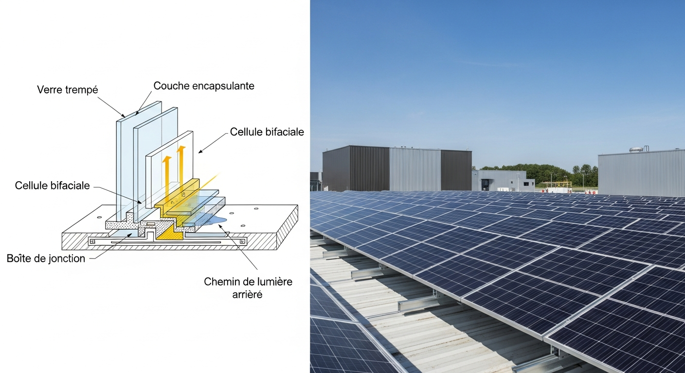
Understanding the superior performance of bifacial panels requires a granular analysis of their physics, efficiency metrics, and integration with power station electronics. Unlike monofacial panels, which utilize an opaque backsheet, bifacial modules employ a transparent backsheet (typically dual-glass or transparent polymer) to allow ambient and reflected light to reach the rear side of the solar cells.
Physics of Bifacial Energy Conversion and Albedo Effect
The core principle is the capture of photons on two surfaces. The front side operates identically to a monofacial panel, converting direct and diffuse irradiance into DC current. The rear side, however, capitalizes on the albedo effect—the measure of light reflectivity of a given surface. Light that passes the panel or is reflected from the ground (or mounting surface) strikes the rear of the cells. A surface with high albedo, like white gravel (albedo ≈ 0.6-0.8) or fresh snow (albedo ≈ 0.8-0.9), can significantly boost rear-side generation.
The bifacial gain is not linear and depends on several factors: albedo, ground clearance height (GCH), and row-to-row spacing (pitch). A higher GCH allows more diffuse light to reach the rear surface, with optimal gains often seen at heights of 1 meter or more, though significant gains are still achievable at lower heights typical of residential or portable setups. The total power output (P_total) is calculated as: P_total = P_front + (P_rear * Bifaciality_Factor). This additional wattage is critical for power stations, as it can provide a sustained charging current when front-side irradiance drops.
Efficiency Benchmarks for 2026 Components
By 2026, cell efficiency is paramount. Monocrystalline n-type cells (both TOPCon and HJT) are the industry standard for bifacial modules due to their low degradation rates and high bifaciality. While p-type PERC cells can be made bifacial, their higher susceptibility to Light Induced Degradation (LID) and lower bifaciality factor (typically 70-75%) make them a budget-tier option.
A premium 2026 bifacial module exhibits a front-side efficiency of 23-24%. The bifaciality factor for an HJT or TOPCon cell is often 85-95%, meaning the rear side operates at nearly the same efficiency as the front. This is a stark contrast to older technologies. This high efficiency directly impacts the Voltage at Maximum Power (Vmp) and Current at Maximum Power (Imp), the key parameters for a power station’s Maximum Power Point Tracking (MPPT) charge controller.
The MPPT controller is the brain of the power station’s solar input. Its function is to continuously adjust the electrical load to find the voltage and current combination that extracts the maximum possible power from the panel. A wider MPPT voltage range (e.g., 11-150V in high-end units like the EcoFlow DELTA Pro) allows for greater flexibility in array configuration and better performance in low-light conditions, where panel voltage can drop significantly. The additional current from bifacial gain keeps the panel operating closer to its Imp, maximizing the wattage delivered to the battery.
Load Calculation and Sizing Strategies for Power Stations
Sizing a bifacial array for a power station requires a more nuanced approach than with monofacial panels. The goal is to maximize charging speed without exceeding the power station’s input voltage (Voc) or current (Isc) limits.
Step 1: Define Energy Demand. Calculate your daily energy consumption in Watt-hours (Wh). For a power station like a Bluetti AC200MAX with a 2,048Wh capacity, a full recharge from solar is the target. A typical load might include a portable refrigerator (50W, 50% duty cycle = 600Wh/day), laptop charging (65W for 4 hours = 260Wh/day), and LED lights (10W for 5 hours = 50Wh/day), totaling 910Wh.
Step 2: Calculate Required Solar Generation. To generate 910Wh, assuming 4 peak sun hours (a conservative estimate for many regions), you need 910Wh / 4h = 227.5W of consistent power. A standard 400W monofacial panel might achieve this under ideal conditions. However, a 400W bifacial panel, with a conservative 15% bifacial gain, provides an effective power of 400W * 1.15 = 460W. This surplus power is crucial for charging the battery faster and for offsetting system losses (inverter, wiring, etc.).
Step 3: Match Panel to MPPT. Consider a 450W bifacial panel with Vmp = 42V and Imp = 10.7A. With a 15% gain, the effective Imp could rise to ~12.3A. The power station’s MPPT must have a voltage window that includes 42V and a current limit above 12.3A. If you connect two such panels in series, the voltage doubles (Voc_total = Voc1 + Voc2) while the current remains the same. This is often done to meet the higher voltage requirements of larger power stations and reduce voltage drop over long cable runs, a critical consideration for efficiency.
Engineering Specifications & Innovations in 2026
The bifacial market in 2026 is characterized by intense competition and rapid innovation, not just in cell technology but in module construction and system integration. Leading brands are pushing the boundaries of what’s possible for both large-scale and portable power applications.
Cell and Module Level Innovations
N-Type HJT & TOPCon Dominance: As predicted, n-type cells are the de facto standard. HJT (Heterojunction) technology, championed by brands like Panasonic and REC, offers exceptional temperature coefficients (as low as -0.24%/°C) and high bifaciality (~90-95%). This means they perform better in hot climates and generate significant rear-side power. TOPCon (Tunnel Oxide Passivated Contact) technology, adopted by giants like Jinko Solar and LONGi, offers a more cost-effective path to high efficiency and bifaciality (~85-90%), making it the volume leader.
Perovskite-Silicon Tandem Cells: While not yet mainstream in the consumer market, 2026 sees the first commercial applications of perovskite-on-silicon tandem cells in specialized, high-end modules. These cells layer a perovskite cell on top of a traditional silicon cell, allowing them to capture different wavelengths of light. This pushes theoretical efficiency limits beyond 30%. For portable power, a lightweight, flexible bifacial panel using this technology could offer unprecedented power-to-weight ratios, though at a significant cost premium.
Glass-Glass vs. Transparent Backsheet: The dual-glass (or glass-glass) module construction offers superior durability, fire resistance (Class A), and lower degradation over a 30-year lifespan. This makes them ideal for permanent home backup systems. For portable power stations, manufacturers like EcoFlow and Bluetti offer bifacial panels with a transparent polymer backsheet, which significantly reduces weight and improves portability without sacrificing too much of the bifacial gain.
Brand-Specific System Integration
EcoFlow’s Bifacial Ecosystem: EcoFlow has fully integrated bifacial technology into its product line. Their 400W and 220W portable bifacial panels are designed to pair seamlessly with the DELTA series power stations. The carrying case for their portable panels is ingeniously designed to double as a reflective stand, optimizing the tilt angle and providing a high-albedo surface to maximize rear-side gain, a prime example of user-focused engineering.
Victron Energy’s Modular Approach: Victron focuses on components for custom systems. A typical 2026 Victron-based setup might pair high-wattage bifacial panels from a third-party manufacturer (e.g., Canadian Solar’s HiKu7 series) with a SmartSolar MPPT charge controller. The VictronConnect app allows for meticulous monitoring of both front and estimated rear-side generation, giving prosumers granular control and performance data. Their systems are engineered for maximum reliability and scalability for serious off-grid applications.
Tesla’s Integrated Vision: While Tesla’s Solar Roof is not bifacial, their strategy influences the market. The integration of solar generation with the Powerwall battery and EV charging creates a unified ecosystem. The demand for higher home energy production to meet these loads drives the adoption of high-yield technologies like bifacial panels on ground mounts or carports, where their performance can be maximized to charge the Powerwall faster.
Technical Comparison of 2026 Bifacial Solar Panel & Power Station Kits
| Kit / Model | Target Application | Panel Specs (Power, Cell Type, Bifaciality) | Power Station Specs (Capacity, MPPT Range) | Key Engineering Feature |
|---|---|---|---|---|
| EcoFlow DELTA Pro + 400W Bifacial | Portable Home Backup / RV | 400W (Front) + 80W (Rear Est.), Monocrystalline, ~85% Bifaciality | 3,600Wh LiFePO4, 11-150V MPPT, 15A Max | Integrated system with a carrying case that doubles as a reflective stand to maximize bifacial gain. |
| Bluetti AC500 & B300S + LONGi Hi-MO 6 | Modular Whole-Home Backup | 580W (Front), HPBC (n-type), ~80% Bifaciality | 3,072-18,432Wh LiFePO4, 12-150V MPPT, 15A per input (2 inputs) | Dual MPPT inputs allow for separate arrays (e.g., east/west facing) to optimize all-day bifacial harvest. |
| Victron EasySolar-II GX + Canadian Solar TopHiKu6 | Off-Grid Cabin / Prosumer | 575W (Front), n-type TOPCon, ~85% Bifaciality | Component-based (e.g., 5,000Wh), MPPT up to 250V, 70A | High-voltage MPPT allows for long series strings, minimizing voltage drop and maximizing efficiency for large arrays. |
| Anker SOLIX F3800 + 400W Bifacial Panel | Home Backup with EV Charging | 400W (Front), Monocrystalline, ~80% Bifaciality | 3,840Wh LiFePO4, 30-150V MPPT, 25A Max | High current MPPT input (25A) is well-suited for parallel connections of high-current bifacial panels. |
| Jackery Explorer 2000 Plus + SolarSaga 200W Bifacial | Lightweight Portable / Camping | 200W (Front), Monocrystalline, ~80% Bifaciality | 2,042Wh LiFePO4, 11-60V MPPT, 12A x 2 inputs | Extreme portability and fast setup. IP68 rated panels for durability in harsh outdoor environments. |
Safety Protocols and Engineering Standards for Bifacial Systems
The increased power output and unique construction of bifacial panels necessitate a rigorous adherence to safety standards. A properly engineered system is not only efficient but fundamentally safe. This involves electrical, physical, and fire safety considerations governed by codes like the National Electrical Code (NEC) in the United States.
Electrically, all systems must be designed to handle the maximum possible voltage and current. The open-circuit voltage (Voc) of a panel array must never exceed the maximum input voltage of the power station’s charge controller, especially after accounting for cold temperature effects (Voc increases as temperature drops). NEC Article 690 provides the framework for this, including requirements for rapid shutdown, which is critical for firefighter safety in grid-tied home systems. For portable setups, using properly sized MC4 extension cables with low voltage drop is essential to prevent overheating and power loss.
The physical installation of bifacial panels, particularly on rooftops or ground mounts, must account for wind and snow loads. The dual-glass construction of many bifacial modules makes them heavier than their monofacial counterparts, requiring robust mounting hardware. The mounting system must also be engineered to provide adequate ground clearance to enable bifacial gain while ensuring structural integrity. For portable panels, secure anchoring is vital to prevent them from becoming airborne in high winds.
Ingress Protection (IP) ratings are a key indicator of a component’s resilience to environmental factors. A solar panel with an IP68 rating is fully protected against dust ingress and can withstand continuous immersion in water. The junction box, where electrical connections are made, is a critical point of failure; a high IP rating here is non-negotiable. Power stations themselves typically have lower IP ratings (e.g., IP21), as they are not designed for direct exposure to rain. Ensuring the power station is in a dry, ventilated location while the IP67/IP68 rated panels are outdoors is a fundamental safety practice.
Finally, fire safety is paramount, especially with glass-glass modules being installed on rooftops. These modules often carry a Class A fire rating, indicating the highest resistance to fire spread. This, combined with proper wiring, overcurrent protection (fuses or circuit breakers), and adherence to NEC rapid shutdown requirements, creates a multi-layered safety system that protects both property and personnel.
Pre-Installation Operational Checklist
- Site Assessment: Survey the installation area. Identify a location with maximum sun exposure and minimal shading. For bifacial panels, assess the ground surface albedo—can you place a reflective mat or light-colored gravel to boost rear-side gain?
- System Sizing Verification: Re-confirm your daily Watt-hour (Wh) load calculation. Does your chosen panel array and power station battery capacity provide an adequate buffer (we recommend a 20-30% surplus)?
- Component Compatibility Check: Verify that the total Open Circuit Voltage (Voc) of your panel array (in series) is below the maximum voltage of your power station’s MPPT controller. Check that the array’s Current at Short Circuit (Isc) is below the MPPT’s current limit.
- Structural Integrity: If using a ground or roof mount, confirm that the structure can support the weight of the bifacial panels and withstand local wind and snow load requirements. Ensure the mounting allows for at least 0.5-1 meter of ground clearance for optimal bifacial gain.
- Electrical Bill of Materials: Procure all necessary wiring (correct AWG for current and distance to minimize voltage drop), MC4 connectors, fuses/breakers, and grounding equipment (lugs and copper wire). Ensure all components are UL listed.
- Safety Equipment: Gather personal protective equipment (PPE), including insulated gloves, safety glasses, and appropriate fall protection if working at height. Have a properly rated fire extinguisher (Class C) accessible.
- Power Station Pre-Check: Fully charge the power station from an AC wall outlet before its first solar charge. Verify that the unit powers on and all outputs (AC/DC) are functional. Update its firmware if applicable.
- Review Manuals and Codes: Thoroughly read the installation manuals for both the solar panels and the power station. Familiarize yourself with the relevant sections of NEC Article 690, even for portable systems, as they contain best practices for safety.
Advanced Technical FAQ
What is the practical impact of the temperature coefficient on bifacial panel performance when charging a power station?
The temperature coefficient, typically expressed as %/°C, quantifies how much a panel’s power output decreases for every degree Celsius above the standard test condition temperature of 25°C. For example, a panel with a -0.35%/°C coefficient will lose 3.5% of its power output at 35°C. N-type HJT bifacial panels, with coefficients as low as -0.24%/°C, lose significantly less power in hot conditions compared to p-type PERC panels (-0.35%/°C or higher). This is critical for power stations, as peak sun often coincides with peak heat. The HJT panel will maintain a higher voltage (Vmp) and current (Imp), allowing the MPPT controller to deliver more charging wattage to the battery during the hottest, sunniest parts of the day, directly reducing charging time.
How does a bifacial panel’s series/parallel configuration affect the MPPT efficiency of a power station?
Configuring panels in series increases the total voltage while keeping current constant. This is beneficial for overcoming voltage drop in long cable runs and for meeting the minimum operational voltage of high-power MPPT controllers (like those from Victron). However, in a series string, the entire string’s current is limited by the lowest-performing panel (e.g., one that is partially shaded). Configuring in parallel increases current while keeping voltage constant. This is more tolerant to partial shading on one panel but can result in higher resistive losses (I²R losses) due to the higher current. For bifacial panels, where rear-side gain can be non-uniform, a parallel configuration or the use of multiple MPPT inputs (as on the Bluetti AC500) can sometimes yield better overall energy harvest by isolating panels with different rear-side irradiance levels.
Can I use a bifacial panel with a PWM charge controller instead of an MPPT?
While technically possible, it is highly discouraged and inefficient. A Pulse Width Modulation (PWM) controller essentially connects the solar panel directly to the battery, forcing the panel to operate at the battery’s voltage. This voltage is almost always far from the panel’s Vmp, causing a significant power loss (typically 15-30%). For a high-performance bifacial panel, this negates the benefits of both its high front-side efficiency and any bifacial gain. An MPPT controller is essential to harvest the maximum power by allowing the panel to operate at its optimal Vmp/Imp point, making it a mandatory component for any serious power station setup utilizing bifacial technology.
What is the “bifaciality factor” and why is it higher in n-type cells like HJT and TOPCon?
The bifaciality factor is the ratio of the rear side’s power generation efficiency to the front side’s efficiency under the same illumination. A factor of 85% means the rear can produce 85% of the power of the front. N-type silicon wafers have a fundamentally different charge carrier dynamic (electrons are the majority carriers) compared to p-type wafers. This results in a much longer minority carrier lifetime, which is crucial for collecting the electrons generated by light on the rear side of the cell before they recombine. Furthermore, the cell structures of HJT and TOPCon are more symmetrical, with effective passivation on both the front and rear surfaces, minimizing electrical losses on both sides and leading to superior bifaciality factors (85-95%) compared to bifacial p-type PERC (70-80%).
How do I accurately model the expected bifacial gain for a specific installation height and albedo?
Accurate modeling requires sophisticated software like PVsyst or SAM (System Advisor Model) from NREL. These tools use complex view factor calculations and ray-tracing algorithms to model the amount of irradiance reaching the rear of the module. Key inputs include the panel’s tilt angle, azimuth, ground clearance height (GCH), and the albedo of the ground surface. As a rule of thumb for preliminary calculations: a GCH of 1 meter over grass (albedo ~0.2) might yield a 5-10% gain. The same setup over a white TPO roof or white gravel (albedo ~0.8) could yield a 20-28% gain. For portable panels placed directly on the ground, the gain is minimal unless a reflective mat is used.
📥 Associated Resource:

El Kouriani Abde Civil Engineer & Founder of SolarKiit
El Kouriani Abde is a seasoned Civil Engineer and Project Manager with over 21 years of field experience. As the founder and publisher of SolarKiit.com, he leverages his deep technical background to simplify complex renewable energy concepts. His mission is to provide homeowners and professionals with accurate, engineering-grade guides to maximize their solar investments and achieve energy independence.