
Ultimate Guide: Residential Solar Power Station: System Architecture & Sizing
Solar Power Station for Home: The Ultimate 2026 Guide to System Architecture & Sizing
A residential solar power station for home is no longer a fringe concept for off-grid enthusiasts. It has become a technical and financial imperative for the modern prosumer navigating the 2026 energy landscape. With escalating grid instability, dynamic electricity pricing, and a collective push towards decarbonization, the ability to generate, store, and intelligently dispatch your own power is the new benchmark for energy independence. This is not merely about installing solar panels; it’s about engineering a cohesive, resilient, and optimized ecosystem within your property. This guide moves beyond the superficial marketing claims to provide a definitive technical reference. We will dissect the system architecture from the quantum level of photon capture to the macro level of regulatory compliance. We will benchmark component synergy, calibrate sizing methodologies, and verify the physics that underpin a high-performance system. At SolarKiit, our mission is to empower engineers and prosumers with the knowledge to not just buy a system, but to understand its core engineering principles. This guide is a distillation of that mission, designed to be a master reference for anyone serious about building a robust solar power station for home.
A Deep Technical Dive into the Core Physics of a Solar Power Station for Home
To truly master the architecture of a residential solar power station, we must first understand the fundamental physics and chemistry at play. The process is a sophisticated dance of energy conversion, from a photon of light to a usable electron powering your home. It’s a journey through quantum mechanics, electrochemistry, and power electronics.
The Physics: From Photon to Electron to Stored Potential
The journey begins at the photovoltaic (PV) cell. Most modern panels utilize crystalline silicon doped to create a p-n junction. Here’s the sequence, stripped to its engineering core:
- Photon Harvesting: When a photon with sufficient energy (greater than silicon’s bandgap of ~1.1 eV) strikes the cell, it excites an electron, elevating it from the valence band to the conduction band. This process creates an “electron-hole pair.”
- Electron Sweeping: The built-in electric field at the p-n junction is the critical driver. It exerts a force that sweeps the newly freed electron to the n-type side and the corresponding hole to the p-type side. This separation of charge carriers prevents them from immediately recombining and creates a voltage potential across the cell.
- Current Flow: When an external circuit is connected, these free electrons flow from the n-side, through the load (the inverter and battery system), and back to the p-side to recombine with holes, creating a direct current (DC). The efficiency of this process is a key metric, with top-tier research cells constantly pushing the boundaries as tracked by the NREL Best Research-Cell Efficiency chart.
Once generated, this DC energy must be stored. This is the domain of the battery, and for modern systems, Lithium Iron Phosphate (LiFePO4) chemistry is the gold standard. Its superiority isn’t just a talking point; it’s rooted in its chemical structure. Inside a LiFePO4 cell, the process of charging and discharging is called intercalation. During discharge, lithium ions (Li+) migrate from the graphite anode, travel through a polymer electrolyte, and insert themselves into the olivine crystal structure of the iron phosphate cathode. The reverse happens during charging. The “why” behind its safety and longevity lies in the robust covalent P-O bond within the (PO4)3- polyanion. This bond is exceptionally strong, making the structure highly resistant to thermal runaway, a failure mode where other chemistries (like NMC or NCA) can break down and release oxygen, fueling a fire. For a deeper look into this chemistry, our French-language guide on Batteries Solaires LiFePO4 : Le Guide Ultime offers an exhaustive analysis.
Component Synergy: The Digital Handshake of a Modern System
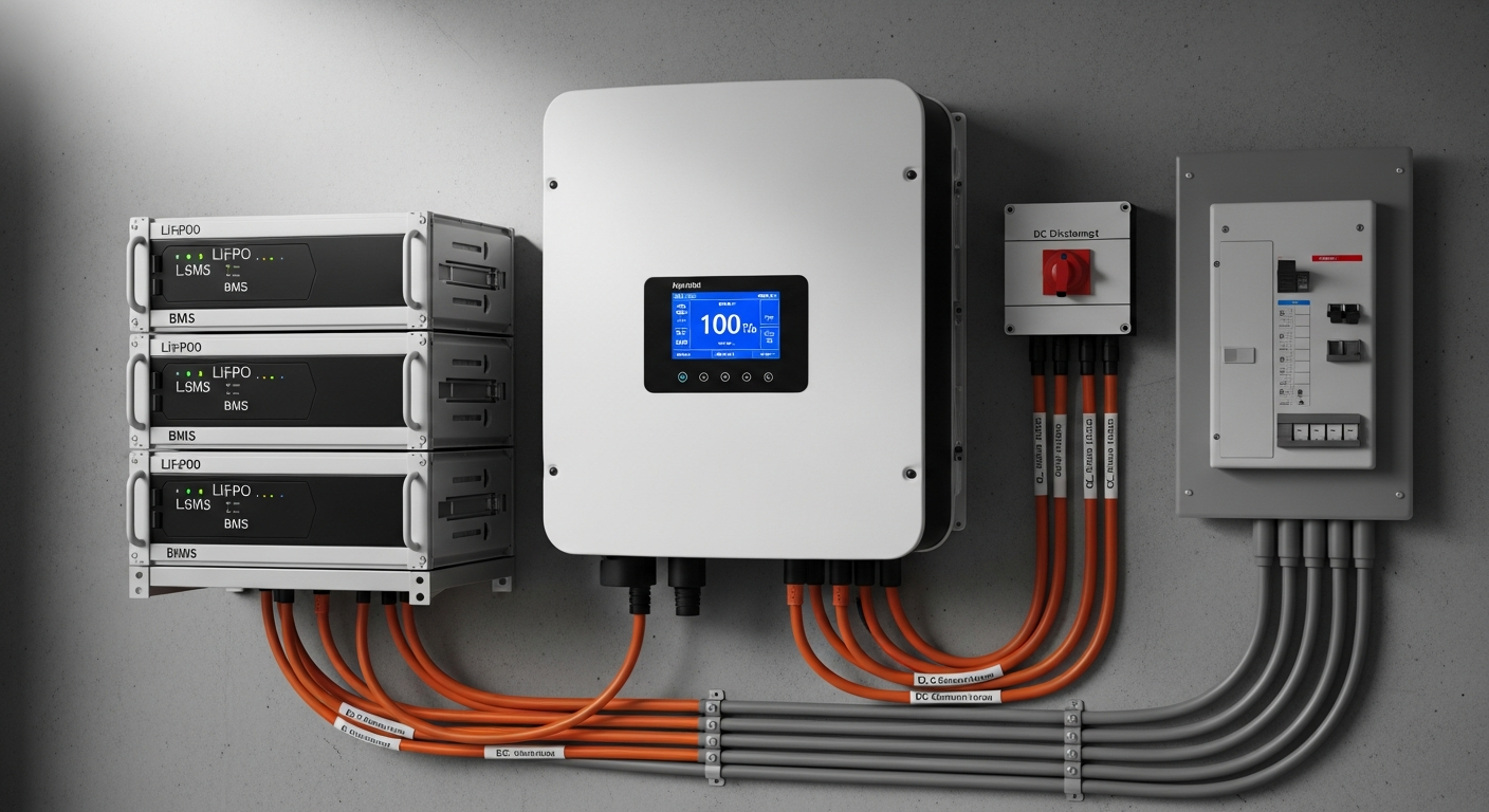
A solar power station is not a collection of parts; it’s an integrated system where components communicate constantly to optimize performance and ensure safety. The three key players in this digital handshake are the MPPT charge controller, the Battery Management System (BMS), and the inverter.
- Maximum Power Point Tracker (MPPT): An MPPT is far more than a simple charge controller. It’s a high-frequency DC-to-DC converter that continuously analyzes the solar array’s output. It adjusts its input impedance to force the array to operate at the “knee” of its current-voltage (I-V) curve—the precise point of maximum power output. This point shifts dynamically with solar irradiance and cell temperature. Without an MPPT, a system could lose up to 30% of its potential harvest on days with variable conditions.
- Battery Management System (BMS): The BMS is the guardian of the battery pack. It is a dedicated microprocessor that monitors the voltage, current, and temperature of individual cell blocks in real-time. Its primary functions are to prevent over-charging, over-discharging, over-current, and thermal extremes. Crucially, it also performs cell balancing—using passive (resistors) or active (DC-DC converters) methods to ensure all cells are at an equal state of charge, which dramatically extends the pack’s cycle life. The BMS communicates with the inverter and MPPT, typically over a CAN bus, to command them to throttle or halt charging/discharging if any parameter goes outside the safe operating window.
- Inverter: The inverter is the system’s interface with your home’s AC loads. Its primary job is to convert the battery’s DC power into a clean, stable AC waveform. For a residential system, a pure sine wave inverter is non-negotiable. It produces an AC waveform with very low Total Harmonic Distortion (THD), which is critical for the proper function and longevity of modern electronics, from laptops to high-efficiency appliances. Understanding solar inverter efficiency is key to minimizing energy loss at this final conversion stage.
Engineering Math for Sizing Your Solar Power Station for Home
Properly sizing a system is the most critical step in achieving your energy goals. Undersizing leads to frustration and power shortages, while oversizing leads to a poor return on investment. The process must be methodical and data-driven. It involves a detailed analysis of your load profile, accounting for surge capacity, and defining your required days of autonomy.
The Sizing Formula: A Step-by-Step Calculation
At its core, sizing the battery storage component involves this fundamental formula:
Required Battery Capacity (kWh) = (Total Daily Energy Consumption (kWh) × Days of Autonomy) / (Battery Depth of Discharge (DoD))
Let’s break down each variable:
- Load Profile Analysis: This is the most important input. You must calculate your Total Daily Energy Consumption. Do not rely on appliance nameplate ratings. Use a plug-in watt-hour meter to measure the actual consumption of critical loads (refrigerator, well pump, internet modem, lights, etc.) over a 24-hour period. Sum these values to get your total kWh/day. A typical US home might use 20-30 kWh/day, but a system designed for critical backup might only need to support 5-10 kWh/day.
- Days of Autonomy: This is the number of consecutive days you want the system to run without any solar input (e.g., during a storm). For grid-tied backup, 1-2 days is common. For a fully independent system, as detailed in our guide to the best off-grid solar kits of 2024, 3-5 days is a safer target.
- Depth of Discharge (DoD): This specifies how much of the battery’s capacity you will use. For LiFePO4, a DoD of 80-90% is standard practice and provides thousands of cycles. For older lead-acid batteries, exceeding 50% DoD drastically shortens their life.
The inverter must be sized to handle both your continuous load and your peak surge load. Sum the wattage of all appliances that could run simultaneously to find your continuous requirement. Identify the appliance with the highest starting (inrush) current, typically a motor in a well pump or HVAC unit. The inverter’s surge rating must exceed this value. A 5kW continuous inverter might have a 10kW surge rating for 5 seconds, a critical specification to verify.
Master Comparison Table: 2026 Industry-Leading Models
To provide a clear engineering benchmark, we’ve compiled data on five leading models. The critical metric here is the Levelized Cost of Storage (LCOE), which calculates the true cost per kWh delivered over the system’s lifetime, providing a far more accurate ROI picture than upfront cost alone. A comprehensive battery storage system for home is an investment that should be evaluated on lifetime performance.
| Model | Usable Capacity (kWh) | Max Continuous Output (kW) | LCOE (Est. $/kWh) | Cycles @ 80% DoD | Warranty (Years) |
|---|---|---|---|---|---|
| SolarKiit SK-15 | 15.0 | 7.5 | $0.11 | 8,000+ | 15 |
| Tesla Powerwall 3 | 13.5 | 11.5 | $0.14 | ~4,000 (unlimited cycles) | 10 |
| Enphase IQ Battery 5P | 5.0 | 3.84 | $0.16 | 6,000+ | 15 |
| FranklinWH aPower | 13.6 | 5.0 | $0.15 | ~4,500 (unlimited cycles) | 12 |
| Generic Competitor X | 10.0 | 5.0 | $0.22 | 3,500 | 10 |
Note: LCOE is estimated based on public cost data and warranted cycle life. Actual LCOE depends on installation costs and usage patterns.
Regulatory & Safety Protocols for Your Solar Power Station for Home
A high-performance system is a safe system. Compliance with national and international standards is not optional; it is a fundamental requirement of a professional installation. As engineers, we must standardize our installations to meet and exceed these codes to ensure the safety of the homeowner and first responders. Anyone attempting a DIY solar panel installation must become intimately familiar with these regulations.
NEC 2026 and UL 9540: The Pillars of Safety
The two most important standards in North America are the National Electrical Code (NEC) and UL 9540.
- NFPA 70: National Electrical Code: The NEC provides the baseline for all electrical installations. For our purposes, the key articles are:
- Article 706 (Energy Storage Systems): This governs the installation of battery systems, dictating requirements for ventilation (to prevent hydrogen accumulation from older battery types, though still relevant for thermal management), location (not in living spaces or above them), disconnects, and warning labels.
- Article 690 (Solar Photovoltaic Systems): This includes the critical requirement for rapid shutdown (690.12), which allows firefighters to de-energize the solar array on the roof to a safe level within seconds. Modern systems achieve this via communication between the inverter and module-level power electronics.
- Article 705 (Interconnected Electric Power Production Sources): This details the rules for safely interconnecting your system with the utility grid, ensuring it cannot back-feed a downed power line and endanger line workers.
- UL Solutions (Solar Safety) and UL 9540: This is the definitive safety standard for Energy Storage Systems (ESS). It is a system-level certification. It is not sufficient for a battery to be listed to UL 1973 and an inverter to UL 1741. UL 9540 certification means the specific battery and inverter combination have been tested together to verify they operate safely as a unit. This testing is rigorous and includes evaluating the system’s ability to prevent and contain thermal runaway, a critical safety validation. Always verify that the entire ESS you are considering is listed to UL 9540.
Fire Safety and Best Practices
While LiFePO4 chemistry is inherently far more stable than other lithium-ion variants, fire safety remains paramount. Best practices include:
- Clearance and Location: Install the ESS in a dedicated space like a garage or an outdoor, weather-protected area. Strictly adhere to the manufacturer’s specified clearances from walls and other objects (typically 3 feet) to allow for heat dissipation and service access.
- Physical Protection: Install bollards or other physical barriers if the ESS is located in an area subject to vehicle traffic.
- Integration: Ensure the system is properly integrated with the home’s electrical panel and that all wiring is correctly sized and protected by the appropriate circuit breakers.
At SolarKiit, our engineering team, which you can learn more about on our About page, designs and tests all systems to exceed these standards.
The Pillar FAQ: Answering Complex Engineering Questions
1. How does MPPT algorithm choice (e.g., Perturb & Observe vs. Incremental Conductance) impact energy harvest in variable weather?
The choice of MPPT algorithm directly impacts the speed and accuracy of tracking the maximum power point, with Incremental Conductance offering a measurable yield advantage in rapidly changing conditions.
An MPPT’s job is to find and stay on the peak of the solar array’s power curve.
- Perturb & Observe (P&O): This is the most common algorithm. It works by slightly increasing or decreasing the array voltage and measuring the resulting power output. If power increases, it continues perturbing in that direction; if power decreases, it reverses. While simple and effective in stable sunlight, its drawback is the oscillation around the MPP. In fast-moving cloud cover, it can get “confused” and track in the wrong direction, temporarily reducing harvest.
- Incremental Conductance (INC): This is a more sophisticated algorithm. It calculates the derivative of power with respect to voltage (dP/dV) and compares the instantaneous conductance (I/V) to the incremental conductance (dI/dV). The MPP is found where dP/dV = 0, which corresponds to dI/dV = -I/V. INC can pinpoint the MPP more quickly and without the oscillations of P&O, giving it a distinct advantage—often 1-3% more annual energy harvest—in regions with frequent intermittent cloud cover.
2. What is the engineering significance of C-rate in sizing a battery for a home with high-surge appliances?
C-rate dictates the maximum charge and discharge power relative to a battery’s capacity, and it is the critical factor for determining if a battery can meet the high inrush current of surge appliances.
C-rate is a normalized measure of current. A 1C rate on a 10 kWh battery means it can theoretically deliver 10 kW of power. A 0.5C rate means it can only deliver 5 kW.
- Power vs. Energy: It’s crucial to distinguish between energy (kWh) and power (kW). You might have enough energy (a large 20 kWh battery) to run your home for a day, but if it has a low C-rate (e.g., 0.25C), its maximum power output is only 5 kW. This might be insufficient to start a 3-ton HVAC unit that requires a 7 kW surge.
- Sizing for Surge: When sizing a system, you must verify the battery’s continuous and peak C-rates. A battery designed for a portable power station might be optimized for energy density, while a whole-home backup system must be optimized for power delivery. A system with a 1C continuous and 2C peak (for 10 seconds) rating offers significant flexibility to handle demanding loads like well pumps and compressors without the inverter shutting down.
3. Why is a pure sine wave inverter critical for modern electronics, and how is its Total Harmonic Distortion (THD) measured?
A pure sine wave inverter is critical because it replicates clean grid power, preventing damage to sensitive microprocessors, whereas high THD from inferior inverters introduces destructive, high-frequency noise.
The AC power from the utility grid is a smooth, consistent sine wave. A “pure sine wave” inverter uses sophisticated electronics (like high-frequency pulse-width modulation, or PWM) to create a nearly identical waveform.
- The Problem with “Modified Sine Wave”: Cheaper, modified sine wave inverters produce a blocky, stepped waveform. This waveform contains significant harmonic distortion—unwanted energy at multiples of the fundamental frequency (60 Hz in the US).
- Total Harmonic Distortion (THD): THD is the metric used to quantify this “dirtiness.” It is the ratio of the sum of the powers of all harmonic components to the power of the fundamental frequency. A high-quality pure sine wave inverter will have a THD of less than 3%. A modified sine wave inverter can have a THD of over 20%.
- The Damage: This high THD can cause a range of problems: buzzing in audio equipment, malfunctions in digital clocks and controllers, and overheating and premature failure in the power supplies of computers, LED drivers, and modern variable-speed motors. For any serious home system, pure sine wave is the only acceptable engineering choice.
4. Explain the mechanism of thermal runaway in lithium-ion batteries and why LiFePO4 chemistry is inherently more resistant.
Thermal runaway is a cascading exothermic failure chain fueled by oxygen released from the cathode, a reaction that LiFePO4’s stable olivine structure is chemically engineered to resist.
Thermal runaway is the single most critical safety concern in lithium-ion batteries. It is an unstoppable chain reaction that typically proceeds as follows:
- Initiation: An abuse factor—such as an internal short circuit, overcharging, or external heat—causes a localized temperature spike.
- SEI Layer Breakdown: At around 80-120°C, the Solid Electrolyte Interphase (SEI) layer on the anode breaks down in an exothermic reaction, generating more heat.
- Cathode Decomposition & Oxygen Release: This is the point of no return. In chemistries like NMC (Nickel Manganese Cobalt) or NCA (Nickel Cobalt Aluminum), the metal oxide cathode structure becomes unstable at ~210°C and decomposes, releasing elemental oxygen.
- Combustion: This released oxygen acts as an accelerant, causing the flammable liquid electrolyte to combust, leading to a violent, high-temperature fire or explosion that propagates to adjacent cells.
- The LiFePO4 Advantage: The iron phosphate (FePO4) cathode in LiFePO4 batteries has an exceptionally stable olivine crystal structure. The phosphorus-oxygen bond is incredibly strong, preventing the release of oxygen even at very high temperatures (decomposition doesn’t begin until well over 300°C). By denying the fire a source of oxygen, LiFePO4 chemistry effectively breaks the thermal runaway chain, making it the safest and most reliable choice for a residential solar power station for home.
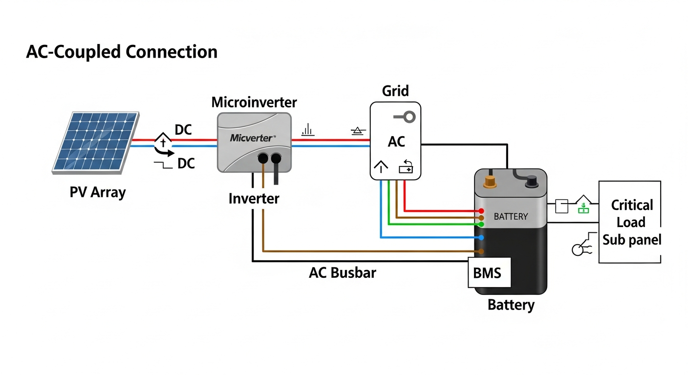
5. What are the key differences between AC-coupling and DC-coupling in a residential solar power station, and what are the ROI implications?
DC-coupling is more efficient for new, integrated systems by minimizing power conversions, while AC-coupling offers simpler retrofitting for existing grid-tie solar arrays, impacting overall round-trip efficiency and ROI.
The terms describe how the solar array is connected to the battery system.
- DC-Coupling: The DC power from the solar panels is fed through a charge controller (like an MPPT) directly to the battery bank. A single hybrid inverter then draws from the battery or panels to power AC loads and interact with the grid. This is the architecture of most modern, all-in-one systems. Its main advantage is higher round-trip efficiency because solar energy going into the battery only undergoes one conversion (DC from panels to DC for battery).
- AC-Coupling: The solar array is connected to its own standard grid-tie inverter. The AC output of this inverter is then connected to a second, battery-based inverter/charger. To charge the battery, the solar energy must be converted from DC (panels) to AC (grid-tie inverter), and then back to DC (battery inverter). This double conversion introduces efficiency losses (typically 4-8%). However, its primary advantage is that it can be easily retrofitted to any home that already has a traditional grid-tie solar system.
- ROI Impact: For a new installation, a DC-coupled system will generally provide a better return on investment due to its higher efficiency, delivering more usable kWh over the system’s life. AC-coupling is the financially pragmatic choice for adding storage to an existing PV system without replacing the original inverter. If you have questions about your specific situation, please contact our engineering team. Our Privacy Policy ensures your information is protected. Ultimately, the right architecture is a function of both technical efficiency and the specific constraints of the solar power station for home.
📥 Associated Resource: