solar power station | Guide Technique d’Ingénierie & Installation 2026

solar power station represents the vanguard of our global transition towards sustainable power, and by 2026, its technological landscape has evolved into a highly sophisticated and efficient ecosystem. The market is no longer defined simply by panel installation but by the intelligent integration of high-efficiency photovoltaics, advanced energy storage systems (ESS), and smart grid-interactive inverters. This guide serves as a definitive engineering resource, dissecting the critical components and methodologies that define modern solar installations.
In 2026, the industry is characterized by the widespread adoption of TOPCon and HJT cell technologies, pushing standard module efficiencies well beyond the 24% mark. The proliferation of lithium iron phosphate (LiFePO4) batteries has made robust, long-cycle energy storage a standard feature, not an optional add-on. For engineers and installers, this means a heightened focus on system-level optimization, from minimizing voltage drop in DC cabling to programming inverter parameters for optimal grid interaction or off-grid resilience. This technical manual provides the necessary framework for navigating this advanced domain.
We will delve into the physics of next-generation cells, provide benchmarks for system sizing and component selection, and analyze the safety protocols mandated by updated electrical codes. The focus remains on practical, actionable intelligence for deploying systems that are not only powerful but also safe, reliable, and future-proofed for the decades to come. Welcome to the engineering frontier of solar power in 2026.
Deep Technical Analysis of Solar Energy Systems
A granular understanding of a solar energy system begins with the fundamental physics of photovoltaic (PV) conversion. At the heart of every solar panel are semiconductor cells, predominantly crystalline silicon. When photons from sunlight strike the silicon’s p-n junction, they transfer their energy to electrons, creating electron-hole pairs. An internal electric field within the junction then separates these pairs, forcing electrons to flow into the n-type layer and holes into the p-type layer, establishing a voltage potential. This flow of electrons, when directed through an external circuit, constitutes direct current (DC) electricity.
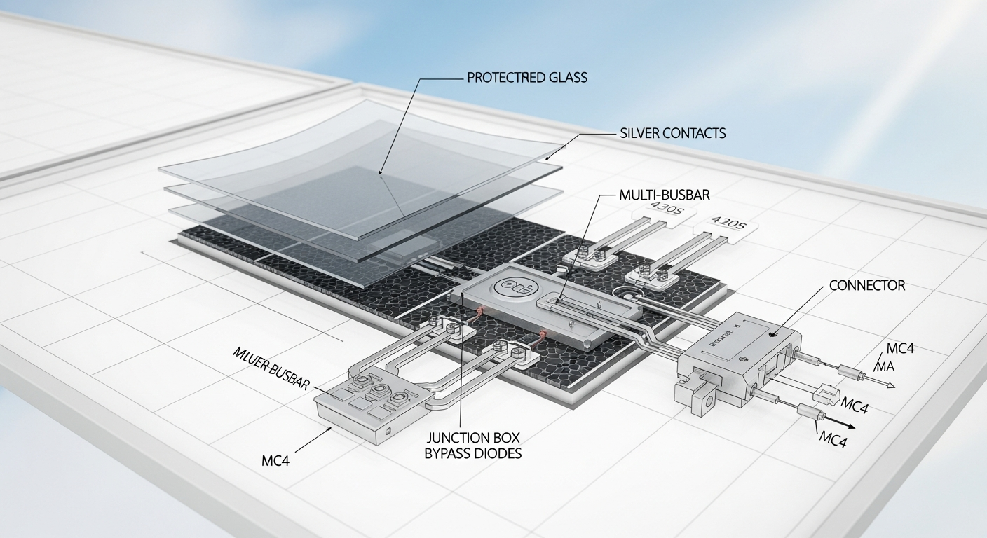
By 2026, the dominant cell architectures have advanced significantly. While Passivated Emitter and Rear Cell (PERC) technology laid the groundwork, Tunnel Oxide Passivated Contact (TOPCon) and Heterojunction (HJT) cells are now the industry benchmarks. TOPCon cells introduce an ultra-thin tunnel oxide layer and a layer of highly doped polysilicon, drastically reducing recombination losses and boosting efficiency. HJT cells combine crystalline silicon with amorphous silicon thin-film layers, achieving superior passivation and temperature coefficients. These advancements have pushed commercially available module efficiencies into the 24-26% range, a significant leap from previous standards.
The performance of the entire system hinges on its components. The inverter, which converts the panel’s DC output to grid-usable alternating current (AC), must be a Pure Sine Wave type to safely power sensitive electronics. Modern hybrid inverters boast efficiencies exceeding 98% and integrate multiple Maximum Power Point Tracking (MPPT) inputs. MPPT algorithms continuously adjust the electrical operating point of the PV array to extract the maximum possible power, adapting in real-time to changing irradiance and temperature. This is critical for maximizing energy harvest throughout the day and in partially shaded conditions.
System sizing is a critical engineering task that begins with a meticulous load calculation. This involves cataloging every AC and DC appliance, its power consumption in watts, and its daily hours of operation to determine the total daily energy requirement in watt-hours (Wh). For a grid-tied system, this informs the target energy offset. For an off-grid system, this number is non-negotiable and must account for seasonal variations.
PV array sizing is then calculated based on this energy demand and the site’s average peak sun hours—a measure of solar insolation. The formula is: Array Size (W) = Daily Energy Demand (Wh) / (Peak Sun Hours x System Derating Factor). The derating factor (typically 0.77-0.85) accounts for real-world losses from temperature, wiring, inverter inefficiency, and soiling. Proper PV orientation (true south in the Northern Hemisphere) and tilt angle are paramount for maximizing annual production.
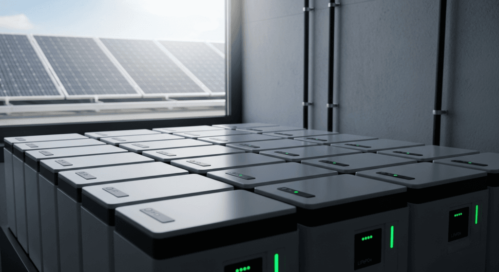
Battery bank sizing is equally crucial for systems requiring energy storage. The primary chemistry is LiFePO4 due to its high cycle life (5,000-10,000 cycles), excellent thermal stability, and high depth of discharge (DoD) of 90-100%. To size a battery bank, one calculates the required capacity in Ampere-hours (Ah) using the formula: Capacity (Ah) = (Daily Energy Demand (Wh) / System Voltage (V)) / Max DoD. This calculation must also incorporate the desired days of autonomy—the number of days the system can operate without any solar input.
Engineering Specifications & Innovations in Solar Energy
The 2026 solar market is driven by sophisticated, integrated technologies from leading manufacturers. These brands differentiate themselves not just on raw power, but on system intelligence, modularity, and user-centric engineering. Understanding these specific ecosystems is key to designing optimal solutions for residential, commercial, or off-grid applications.
Victron Energy continues its dominance in the professional off-grid and marine sectors with its component-based philosophy. A typical Victron system is built around a MultiPlus-II inverter/charger, which seamlessly blends power from solar, battery, grid, and generator sources. This is paired with SmartSolar MPPT charge controllers, which offer industry-leading tracking speed and efficiency. The power of the Victron ecosystem lies in its GX device family (like the Cerbo GX) and the Victron Remote Management (VRM) portal, allowing for deep system configuration and remote monitoring of every parameter, from battery state-of-charge to historical production data.
Conversely, brands like EcoFlow and Bluetti have perfected the modular, high-power “power station” approach. The EcoFlow DELTA Pro Ultra, for instance, is a stackable system offering immense inverter capacity (e.g., 7.2kW continuous, 10.8kW peak) and scalable LiFePO4 battery storage. These systems are engineered for rapid deployment, featuring integrated MPPTs, high-speed AC charging, and user-friendly app control. Their primary innovation is simplifying complex solar installations into a plug-and-play, yet powerful, home backup or portable power solution.
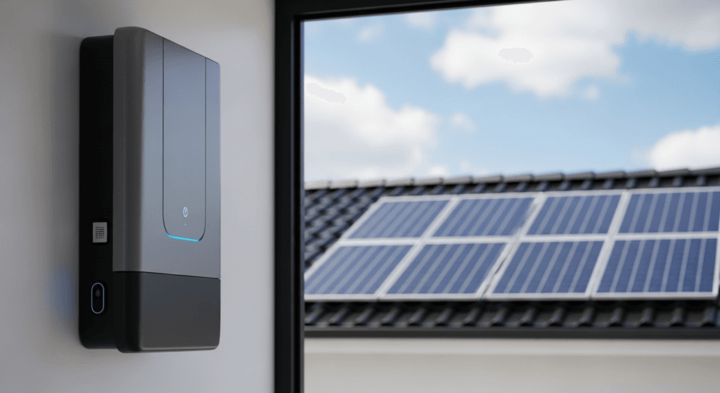
Tesla’s ecosystem remains a benchmark for seamless residential integration. The Tesla Powerwall 3, a 2026 staple, integrates a powerful hybrid inverter directly within the battery unit. This design simplifies installation by reducing component count and wiring complexity. Its key engineering advantage is its software, which intelligently manages energy flow between solar production, home consumption, battery storage, and the grid, often optimizing for time-of-use electricity rates to maximize economic returns for the homeowner.
The most significant innovation at the cell level is the commercial maturation of Perovskite-on-Silicon Tandem Solar Cells. These cells stack a perovskite top cell, which efficiently captures high-energy blue light, on top of a traditional silicon bottom cell that captures lower-energy red light. This multi-junction approach shatters the Shockley-Queisser limit for single-junction silicon cells, with lab efficiencies exceeding 33% and commercial modules beginning to appear with efficiencies of 28-30%. While long-term durability remains a key engineering challenge, their potential for higher power density and lower material cost positions them as the definitive next step in photovoltaic technology.
Technical Comparison of 2026 solar power station System Configurations
| Model / Kit | Cell Type / Panel | Peak Power (Wp) | Module Efficiency | Inverter Type | Battery Chemistry | Key Feature |
|---|---|---|---|---|---|---|
| REC Alpha Pure-RX Series | HJT (Heterojunction) | 470W | 23.6% | N/A (Panel Only) | N/A | Superior temperature coefficient and lead-free construction. |
| Victron Off-Grid Pro Kit | TOPCon (Paired) | 5kW+ (Scalable) | ~24.5% | Hybrid (MultiPlus-II) | LiFePO4 | Unmatched modularity and advanced remote system control via VRM. |
| EcoFlow DELTA Pro Ultra | Any (Compatible) | 7.2kW (Inverter) | N/A (System) | Stackable Hybrid | LiFePO4 | High-power plug-and-play design for rapid home backup deployment. |
| Tesla Powerwall 3 System | Any (Compatible) | 11.5kW (Inverter) | N/A (System) | Integrated Hybrid | NMC/LiFePO4 | Seamless software integration with Tesla vehicles and grid services. |
| SolarKiit Perovskite Tandem 500W | Perovskite-on-Silicon | 500W | 28.0% | N/A (Panel Only) | N/A | Cutting-edge efficiency, maximizing power per square foot. |
Safety, Standards, and Compliance
Engineering a solar installation is as much about safety and regulatory compliance as it is about performance. Adherence to the National Electrical Code (NEC) is mandatory. NEC Article 690 provides the foundational requirements for all PV systems, covering everything from circuit sizing and overcurrent protection to grounding and labeling. A critical provision is the requirement for rapid shutdown, which ensures that DC conductors can be de-energized to a safe voltage level (typically under 30V) within seconds. This is a vital safety measure for protecting first responders during an emergency.
Furthermore, NEC Article 705 governs the interconnection of power production sources with the primary utility grid. It dictates the requirements for breakers, disconnects, and the point of connection to ensure the safety and stability of the grid. All inverters intended for grid-tied use must be certified to the UL 1741 standard, which includes anti-islanding protection—a function that automatically disconnects the inverter from the grid during a power outage to prevent back-feeding and protect utility workers.
The physical robustness of components is quantified by Ingress Protection (IP) ratings. An IP65 rating ensures a component is dust-tight and protected against water jets, making it suitable for most outdoor installations. For components in more exposed locations or at risk of temporary immersion, an IP67 or IP68 rating is required. This is especially critical for PV module junction boxes, external disconnects, and microinverters mounted directly on the racking.
Fire safety protocols are paramount. This involves using properly rated and sized wiring (e.g., PV Wire), ensuring all connections are torqued to manufacturer specifications to prevent arcing, and maintaining proper clearance around components like inverters for heat dissipation. Battery installations, particularly indoors, must comply with specific ventilation, spacing, and thermal management requirements outlined in both the NEC and standards like UL 9540 for energy storage systems.
Pre-Installation Operational Checklist
- Site Survey & Shading Analysis: Conduct a thorough pathfinder analysis to identify any potential shading obstructions (trees, chimneys, vents) throughout the day and year.
- Structural Assessment: Verify that the roof structure can support the additional dead load of the PV array and racking system. Obtain a structural engineer’s report if required by the local authority having jurisdiction (AHJ).
- Permitting & Utility Approval: Secure all necessary building and electrical permits from the AHJ and submit an interconnection application to the local utility company before beginning any work.
- Component Verification: Upon delivery, inventory all components against the bill of materials. Check for any shipping damage and verify that model numbers and specifications match the system design documents.
- Electrical System Audit: Inspect the existing main service panel to confirm it has adequate capacity and physical space for the new solar backfeed breaker. Plan the conduit runs from the array to the inverter and from the inverter to the point of interconnection.
- Safety Plan & Equipment Check: Confirm all personal protective equipment (PPE) is available, including fall protection harnesses, insulated gloves, safety glasses, and lock-out/tag-out (LOTO) kits. Review the site-specific safety plan with the entire installation crew.
Advanced Engineering FAQ
Why is calculating voltage drop so critical in a DC solar circuit?
Voltage drop is the reduction in voltage along a conductor due to its inherent resistance. In a DC solar circuit, especially over long wire runs from the PV array to the charge controller or inverter, excessive voltage drop (ideally kept under 2-3%) leads to a direct loss of power (P = V x I). This wasted energy dissipates as heat, reducing overall system efficiency and energy harvest. More critically, if the voltage at the MPPT input drops below its minimum operational window, the controller or inverter may fail to start up or may operate inefficiently, severely crippling system performance.
solar power station: In 2026, is there any reason to use a PWM controller over an MPPT controller?
For virtually all professional installations, a Maximum Power Point Tracking (MPPT) controller is superior. MPPT technology can convert excess PV voltage into higher charging current, boosting harvest by up to 30% over Pulse-Width Modulation (PWM) controllers, especially in cold weather. However, a PWM controller may still be a cost-effective choice for very small, simple systems (e.g., under 200W) where the PV nominal voltage is matched to the battery nominal voltage and the primary goal is trickle charging, not maximizing power generation.
What are the engineering trade-offs between wiring solar panels in series versus parallel?
Wiring panels in series increases the string voltage while keeping the current constant. This is advantageous for reducing wire size (and cost) and minimizing resistive losses (I²R losses) over long distances. However, a series string’s performance is limited by its weakest panel; if one panel is shaded, the entire string’s output drops significantly. Wiring in parallel increases the current while keeping the voltage constant. This provides better shade tolerance, as an underperforming panel does not affect the others. The trade-off is the need for thicker, more expensive cables and a combiner box with fuses to handle the higher amperage.
Why is a Pure Sine Wave inverter mandatory for modern electronics and appliances?
A Pure Sine Wave inverter produces an AC waveform that is identical to or cleaner than the power supplied by the utility grid. Sensitive electronics, such as laptops, LED lighting, variable-speed motors in modern refrigerators, and medical equipment, are designed for this smooth waveform. Using a cheaper Modified Sine Wave inverter can cause these devices to run hot, make buzzing sounds, perform erratically, or suffer permanent damage due to the “blocky” and harmonically distorted nature of its output.
For stationary energy storage, why is LiFePO4 chemistry considered superior to NMC in 2026?
While Nickel Manganese Cobalt (NMC) chemistry offers higher energy density (making it ideal for EVs), Lithium Iron Phosphate (LiFePO4) is superior for stationary storage due to three key engineering factors. First, it has a significantly longer cycle life, often 2-3 times that of NMC, providing a lower total cost of ownership. Second, LiFePO4 has exceptional thermal stability, making it far less prone to thermal runaway and fire. Third, it does not use cobalt, a conflict mineral with high environmental and ethical sourcing costs, making LiFePO4 the more sustainable and stable supply chain choice.
In conclusion, the successful engineering and installation of a 2026-era photovoltaic system demand a deep, multi-disciplinary expertise. It requires a mastery of semiconductor physics, precise electrical calculations, and a robust understanding of evolving safety codes and brand-specific technologies. By prioritizing high-efficiency components, meticulous system sizing, and unwavering adherence to safety standards, we can continue to deploy powerful and resilient systems. This commitment to technical excellence is what will propel the future of Solar Energy and solidify its role as the cornerstone of our clean energy infrastructure.
📥 Associated Resource:

El Kouriani Abde Civil Engineer & Founder of SolarKiit
El Kouriani Abde is a seasoned Civil Engineer and Project Manager with over 21 years of field experience. As the founder and publisher of SolarKiit.com, he leverages his deep technical background to simplify complex renewable energy concepts. His mission is to provide homeowners and professionals with accurate, engineering-grade guides to maximize their solar investments and achieve energy independence.