Système de stockage par batterie solaire | Guide d’Ingénierie pour l’Autonomie 2026
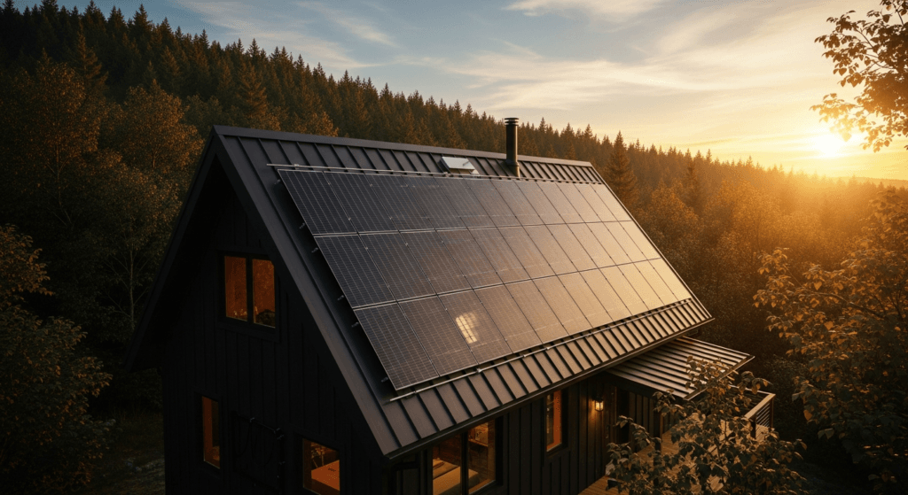
A solar battery storage system represents the cornerstone of modern energy autonomy, evolving far beyond a simple backup utility into a sophisticated energy management hub. By 2026, the integration of these systems is not merely a choice for resilience but a strategic financial and engineering decision. As grid infrastructure faces increasing strain and energy costs become more volatile, a properly engineered system provides insulation from blackouts, optimizes energy tariffs, and enables participation in Virtual Power Plant (VPP) programs.
The landscape is now dominated by high-density Lithium Iron Phosphate (LiFePO4) batteries, advanced hybrid inverters, and intelligent software ecosystems. These components work in concert to maximize self-consumption of solar energy, reducing reliance on the grid to near-zero for extended periods. This guide provides the engineering framework for designing, specifying, and deploying a robust solar battery storage system for complete energy independence in 2026.
We will dissect the core components, from photovoltaic physics to inverter topology, and provide the technical specifications necessary for accurate system sizing. This analysis is critical for ensuring a system not only meets today’s demands but is also scalable and prepared for future technologies like Vehicle-to-Home (V2H) integration. The focus remains on engineering precision, safety compliance, and long-term operational efficiency.
Deep Technical Analysis of a 2026 Solar Battery Storage System
A comprehensive understanding of a solar battery storage system begins with the fundamental physics of energy conversion and flow. The process is a multi-stage sequence, with efficiency at each stage being paramount to the overall system performance. Every component, from the photovoltaic panel to the final AC load, introduces potential losses that must be calculated and mitigated.
Physics of Energy Conversion and System Flow
The journey begins at the photovoltaic (PV) array. In 2026, high-efficiency monocrystalline TOPCon (Tunnel Oxide Passivated Contact) or HJT (Heterojunction) cells are standard, converting photons into DC electricity with efficiencies exceeding 24%. This process, the photovoltaic effect, generates a flow of electrons when solar radiation strikes the semiconductor material. The output is variable DC voltage and current, highly dependent on solar irradiance and cell temperature.
This raw DC power is then routed to a Maximum Power Point Tracking (MPPT) charge controller. The MPPT’s algorithm continuously scans the voltage-current (V-I) curve of the PV array to find the optimal operating point (the “knee” of the curve) that yields maximum power. This is crucial, as a simple PWM controller would force the array to operate at battery voltage, sacrificing significant power. A modern MPPT can boost energy harvest by up to 30% in suboptimal conditions.
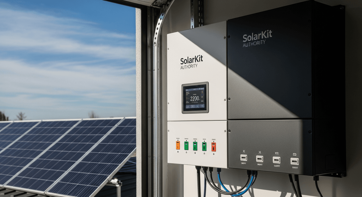
From the charge controller, the regulated DC power has two primary paths. It can directly charge the battery bank or be sent to the inverter. The inverter is the heart of the system, responsible for converting the stored DC energy from the batteries into usable AC electricity. For any modern application, a pure sine wave inverter is non-negotiable. It produces a clean, stable waveform identical to grid power, essential for sensitive electronics, motors, and medical equipment.
Efficiency Benchmarks and System Losses
System efficiency is a product of the efficiencies of its individual components. In 2026, engineering benchmarks are stringent:
- PV Panel Efficiency: 24-26% for premium monocrystalline panels. Perovskite-on-silicon tandem cells are emerging, pushing lab efficiencies toward 33%, with commercial products beginning to appear.
- MPPT Charge Controller Efficiency: >99%. These devices are highly optimized, with minimal conversion loss.
- Battery Round-Trip Efficiency: >95% for LiFePO4 chemistry. This metric measures the energy out versus energy in, accounting for internal resistance and charging/discharging losses.
- Inverter Efficiency: 97-98.5%. This peak efficiency is typically achieved at 50-75% of the inverter’s rated load. It’s critical to analyze the efficiency curve, not just the peak number.
Beyond component efficiency, engineers must account for systemic losses. Voltage drop in cabling is a primary concern; it must be kept below 2-3% by using appropriately sized copper conductors (specified by AWG gauge) for the current and distance. Thermal derating is another factor; inverters, charge controllers, and batteries will reduce their maximum output or charge rate at high ambient temperatures to protect internal components.
Load Calculation and Strategic Sizing
Proper sizing is the most critical phase of system design. An undersized system leads to frustrating power shortages, while an oversized system represents a significant waste of capital. The process is methodical.
1. Load Analysis: First, quantify your daily energy consumption in kilowatt-hours (kWh). Create a detailed load sheet listing every appliance, its power consumption in watts (W), and its daily run time in hours. Sum these to get your total daily kWh. Crucially, differentiate between critical loads (refrigeration, medical devices, well pump) and non-essential loads. The system must be sized to run critical loads for the desired period of autonomy.
2. Battery Bank Sizing (kWh): The battery capacity is determined by your daily critical load consumption and desired days of autonomy (the number of days the system can run without any solar input). The formula is:
Battery Capacity (kWh) = (Daily Energy Consumption (kWh) * Days of Autonomy) / Depth of Discharge (DoD).
For LiFePO4, a DoD of 90-100% is standard, maximizing usable capacity.
3. Inverter Sizing (kW): The inverter must handle the maximum simultaneous power draw. Sum the wattage of all appliances that could run at the same time to determine your peak load. The inverter’s continuous power rating (in kW) should exceed this sum by a safety margin of 20-25%. Also, consider its surge rating, which is its ability to handle the high inrush current of motors starting up.
4. PV Array Sizing (kWp): The solar array must be large enough to fully recharge the battery bank from its maximum DoD and power the daytime loads, typically within one day of average solar conditions. This is calculated using the site’s average Peak Sun Hours (PSH), a measure of solar irradiance.
Array Size (kWp) = Daily Energy Requirement (kWh) / (PSH * System Derating Factor).
The derating factor (typically 0.77-0.85) accounts for all real-world losses like soiling, shading, temperature, and wiring.
Engineering Specifications & 2026 Innovations
The contemporary solar battery storage system is defined by its integration of advanced hardware and intelligent software. Leading manufacturers have moved beyond basic energy storage to create comprehensive energy ecosystems. In 2026, the focus is on modularity, high power density, and bidirectional energy flow.
Tesla’s Powerwall 3+ continues to lead in software integration. Its system leverages machine learning to predict household consumption and solar generation, automatically optimizing battery charge/discharge cycles against time-of-use utility rates. The key innovation is its native support for Vehicle-to-Home (V2H), allowing a compatible EV to act as a massive, mobile extension of the home battery, providing days of additional autonomy.
EcoFlow and Bluetti have championed modularity. Their systems, like the EcoFlow DELTA Pro 2 and Bluetti AC600 series, consist of a central inverter unit with stackable, hot-swappable battery packs. This allows homeowners to start with a smaller capacity (e.g., 5 kWh) and easily expand to 20 kWh or more as their needs or budget grow, without requiring a complete system overhaul. This plug-and-play approach simplifies installation and scalability.
Victron Energy remains the gold standard for off-grid and marine applications, prized for its robust build quality and component-level customization. The MultiPlus-III inverter/charger series offers unparalleled programming flexibility via the VE.Configure software. This allows engineers to fine-tune every parameter, from battery charge voltages to grid-assist thresholds, creating highly specialized systems for complex industrial or remote residential needs.
On the materials science front, the most significant breakthrough is the commercialization of Perovskite-on-Silicon tandem solar cells. By layering a perovskite cell on top of a traditional silicon cell, these panels can capture a wider spectrum of light. This pushes practical module efficiencies toward 30%, meaning a 2026-era 10 kWp array requires significantly less roof space than its 2020 counterpart, a critical advantage for properties with limited area.
2026 Solar Battery Storage System: Technical Comparison
The market offers a range of integrated solutions, each with specific engineering strengths. The following table compares five leading models anticipated for the 2026 market, highlighting key performance indicators for system designers.
| Model (2026 Projection) | Chemistry | Usable Capacity (kWh) | Peak Power (kW) | Round-Trip Efficiency | Key Feature |
|---|---|---|---|---|---|
| Tesla Powerwall 3+ | LiFePO4 | 14.5 kWh | 11.5 kW | 96% | Integrated V2H & Grid Services AI |
| EcoFlow DELTA Pro 2 | LiFePO4 | 5-25 kWh (Modular) | 7.2 kW (expandable to 14.4 kW) | 95.5% | Hot-swappable modular expansion |
| Enphase IQ Battery 15 | LiFePO4 | 15.1 kWh | 7.68 kW | 96.5% | AC-Coupled with integrated microinverters |
| Victron MultiPlus-III Kit | LiFePO4 (Component Agnostic) | Custom (e.g., 20 kWh) | 10 kW | ~95% (System Dependent) | Unmatched off-grid programmability |
| Bluetti AC600 | LiFePO4 | 8-32 kWh (Modular) | 6 kW | 95% | High-capacity modularity for large homes |
Safety Protocols and Compliance Standards
The deployment of a high-voltage DC solar battery storage system mandates strict adherence to safety standards and electrical codes. Negligence in this area can lead to catastrophic equipment failure, fire, and severe personal injury. Engineering for safety is as important as engineering for performance.
The primary governing document in the United States is the National Electrical Code (NEC). Specifically, NEC Article 706 covers Energy Storage Systems (ESS), outlining requirements for installation, disconnection means, and circuit protection. It works in conjunction with NEC Article 705, which details the safe interconnection of power production sources, like a PV system, with the primary power source.
Physical protection of the equipment is quantified by its Ingress Protection (IP) rating. An IP65 rating ensures the enclosure is dust-tight and protected against water jets from any direction, making it suitable for most outdoor installations. For locations prone to flooding or extreme weather, an IP67 rating is superior, guaranteeing protection against temporary immersion in water.
Fire safety is the paramount concern, especially with lithium-ion chemistries. While LiFePO4 is inherently more thermally stable than older chemistries like NMC, thermal runaway is still a risk that must be engineered out. All reputable systems must be certified to UL 9540, the Standard for Energy Storage Systems and Equipment. This certification ensures the entire system—battery, inverter, and controls—has been tested to work together safely.
Furthermore, large-scale battery testing is conducted under UL 9540A, a test method for evaluating thermal runaway fire propagation. The results of this test inform installation requirements, such as minimum clearance between units and walls, to prevent a failure in one unit from spreading. Proper ventilation and adherence to manufacturer-specified operating temperatures are also critical mitigation strategies.
Pre-Installation Operational Checklist
A successful installation begins long before the tools come out. This checklist ensures all critical variables are accounted for, preventing costly delays and errors. It is intended for the homeowner and installation engineer to review together.
- Structural Assessment: Confirm that the proposed mounting location (roof for PV, wall/floor for batteries) can support the additional weight. A structural engineer’s report may be required.
- Electrical Panel Audit: Inspect the main electrical service panel. Is there physical space for new breakers? Does the busbar have the capacity to handle the back-fed solar power? A panel upgrade may be necessary.
- Site Survey & Shading Analysis: Conduct a thorough analysis of the property to identify any potential shading on the PV array throughout the day and year. Even partial shading can severely impact performance.
- Critical Load Definition: Finalize the list of circuits and appliances that will be backed up by the battery. This list directly impacts system sizing and the configuration of the critical load sub-panel.
- Permitting and Utility Approval: Verify all local permitting requirements with the Authority Having Jurisdiction (AHJ). Submit an interconnection application to the local utility company well in advance of installation.
- Component Placement & Clearances: Plan the exact location of the inverter and batteries, ensuring adherence to manufacturer-specified clearances for ventilation and NEC-mandated working space.
- Network & Connectivity Plan: Modern systems require a stable internet connection for monitoring, software updates, and grid services. Confirm Wi-Fi or Ethernet availability at the equipment location.
Advanced Engineering FAQ
What are the engineering trade-offs between AC-coupled and DC-coupled systems?
A DC-coupled system connects the PV array directly to a charge controller, which then charges the battery. The battery power is then sent to a hybrid inverter for use in the home (AC) or to power DC loads. This is highly efficient for new installations, as the PV-to-battery energy transfer has only one conversion step. However, retrofitting an existing grid-tie solar system (which already has a PV inverter) is more complex.
An AC-coupled system, like the Enphase IQ system, adds a battery and a battery-specific inverter to an existing grid-tie PV system. The PV array’s DC power is first converted to AC by its own inverter, and then this AC power is converted back to DC to charge the battery. To be used, it’s converted to AC again. These multiple conversions introduce efficiency losses (typically 5-8% lower round-trip efficiency) but make for a much simpler retrofit of an existing solar installation.
How does ambient temperature critically affect LiFePO4 battery performance and longevity?
LiFePO4 batteries have a preferred operating temperature range, typically 15°C to 25°C (60°F to 77°F). High temperatures (above 40°C / 104°F) accelerate cell degradation, permanently reducing capacity and shortening the battery’s cycle life. Most systems have built-in thermal management (fans or liquid cooling) and will derate (reduce) charge/discharge power to prevent overheating.
Conversely, charging LiFePO4 cells below 0°C (32°F) can cause lithium plating on the anode, which is irreversible and can lead to an internal short circuit. For this reason, all modern Battery Management Systems (BMS) will prevent charging at freezing temperatures. Some premium batteries include integrated heating elements to keep the cells within a safe operating range in cold climates, consuming a small amount of energy to do so.
How does a modern solar battery storage system integrate with EV charging and V2H?
Integration is managed by a central energy management system (EMS). For standard EV charging, the EMS can prioritize using surplus solar power to charge the vehicle, minimizing grid consumption. This is often called “solar-aware charging.” The user can set parameters, such as charging the EV only when the home battery is above 80%.
Vehicle-to-Home (V2H) is more advanced. It requires a bidirectional inverter and a compatible EV. The system treats the EV’s battery (which can be 60-100+ kWh) as a secondary home battery. During a grid outage, the EMS signals the bidirectional inverter to draw DC power from the EV, convert it to AC, and power the home. This dramatically extends energy autonomy without requiring a massive stationary battery.
What is “islanding,” and what specific hardware is required to achieve it safely?
“Islanding” is the ability of a solar and storage system to safely disconnect from the utility grid during an outage and continue to operate independently, forming its own stable, local grid. This is not a default feature and requires specific hardware. The key component is an automatic transfer switch (ATS) or a specific function built into the hybrid inverter.
When the ATS detects a loss of grid voltage, it physically and immediately opens the connection to the utility lines. This is a critical safety feature (anti-islanding) that prevents the home’s system from back-feeding power onto the grid and endangering line workers. Once disconnected, the hybrid inverter begins to form its own stable AC waveform, allowing the home to run on solar and battery power.
How do you calculate the true Levelized Cost of Storage (LCOS) for a system?
LCOS provides a “dollars per kilowatt-hour” metric for the true cost of stored energy over the system’s lifetime, moving beyond the initial sticker price. The formula is:
LCOS = (Total Lifetime Cost) / (Total Lifetime kWh Discharged).
Total Lifetime Cost includes the initial capital expenditure (hardware + installation), any operational costs (e.g., maintenance), and the cost of any replacement components (like an inverter replacement after 10-15 years), minus any incentives or rebates.
Total Lifetime kWh Discharged is calculated by: (Battery Capacity kWh * DoD * Cycles per Day * 365 Days/Year * Warranted Lifespan in Years * Degradation Factor). The degradation factor accounts for the gradual loss of capacity over time. A low LCOS indicates a better long-term investment, and it is a far more accurate metric for comparing systems than simple upfront cost.
In conclusion, the design and implementation of a solar battery storage system in 2026 is a task of precision engineering. By focusing on accurate load analysis, specifying high-efficiency components, and adhering rigorously to safety standards, one can achieve true energy autonomy. The future of residential power is not just about generation, but about intelligent storage and management, and a well-designed solar battery storage system is the definitive solution.
📥 Associated Resource:

El Kouriani Abde Civil Engineer & Founder of SolarKiit
El Kouriani Abde is a seasoned Civil Engineer and Project Manager with over 21 years of field experience. As the founder and publisher of SolarKiit.com, he leverages his deep technical background to simplify complex renewable energy concepts. His mission is to provide homeowners and professionals with accurate, engineering-grade guides to maximize their solar investments and achieve energy independence.