Ultimate Guide: Understanding Round-Trip Efficiency in High-Voltage Energy Storage: A 2026 Engineer’s Guide | SolarKiit
Understanding round-trip efficiency in high-voltage energy storage: The Ultimate 2026 Engineer’s Guide | SolarKiit
Understanding round-trip efficiency in high-voltage energy storage is no longer a peripheral metric for system designers; it is the central pillar upon which the financial viability and engineering integrity of modern renewable energy systems are built. As we accelerate into the 2026 energy transition landscape, the conversation has matured beyond simple kilowatt-hour capacity. Prosumers and engineers alike now demand a granular understanding of performance, where every percentage point of efficiency translates directly into return on investment (ROI), grid resilience, and energy independence. The technical imperative is clear: we must move past datasheet peak ratings and calibrate our focus on the net energy delivered. High-voltage architectures (typically 300-800V DC) represent the frontier of residential and commercial storage, offering profound advantages over legacy 48V systems. However, harnessing this potential requires a deep, physics-based comprehension of the entire energy conversion chain—from photon capture to AC output. This guide is engineered to provide that comprehension. We will dissect the electrochemical processes, benchmark the critical component handshakes, and standardize the mathematical models necessary to design and deploy systems that don’t just store energy, but preserve its value. For those seeking a broader overview of complete systems, our Best Off-Grid Solar Kits of 2026: The Ultimate Guide to Energy Independence provides essential context before this deep dive.
The Physics Behind Understanding Round-Trip Efficiency in High-Voltage Energy Storage
Round-Trip Efficiency (RTE) is the ratio of energy put into a storage system versus the usable energy retrieved from it. A 90% RTE means for every 10 kWh you charge the battery with, you can only discharge 9 kWh. That 1 kWh is lost, primarily as heat. To truly grasp this, we must follow the energy packet’s journey from its origin as a photon to its final form as usable AC power, quantifying the losses at each conversion stage.
From Photon to Electron: The First Law of Thermodynamics in Action
The process begins at the solar panel. While panel efficiency is not part of the storage RTE calculation, it’s the first gatekeeper of energy. Modern TOPCon or HJT cells might achieve 22-24% efficiency under standard test conditions, a figure benchmarked by institutions like NREL Best Research-Cell Efficiency. This means ~77% of the sun’s incident energy is immediately lost as heat and reflected light. The DC electricity generated then flows to the charge controller.
Here, the Maximum Power Point Tracker (MPPT) performs a critical DC-to-DC conversion. It constantly adjusts the electrical operating point of the modules to maximize power output, converting the variable voltage from the panels (which can fluctuate from 30V to 150V+) to the precise voltage required by the high-voltage battery bus (e.g., 400V). This conversion is not lossless; a high-quality MPPT might be 98-99% efficient, but it’s a crucial point of energy attrition before the battery is even engaged.
The Electrochemical Toll: Intercalation in LiFePO4
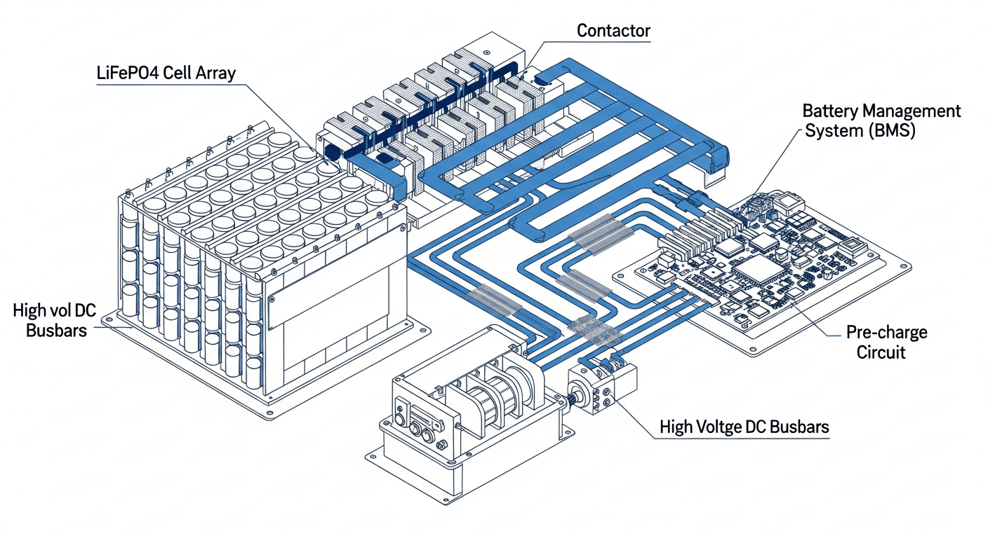
Once the energy reaches the battery terminals, the physics of electrochemistry takes over. In a Lithium Iron Phosphate (LiFePO4) cell—the dominant chemistry for stationary storage due to its safety and cycle life—charging is a process of de-intercalation at the cathode and intercalation at the anode. Lithium ions (Li⁺) are forcibly extracted from the FePO4 crystal lattice of the cathode and travel through the electrolyte to embed themselves within the graphite layers of the anode. This process requires overcoming the battery’s internal resistance, which generates I²R losses (Joule heating). The energy is now stored as chemical potential.
During discharge, the process reverses. Li⁺ ions spontaneously travel back from the anode to the cathode, releasing electrons to the external circuit. This journey is also subject to internal resistance, generating more heat. The sum of these charging and discharging thermal losses is the primary driver of the battery’s own RTE, which for a premium LiFePO4 pack is typically around 95-98%.
Component Synergy: The Digital Handshake That Governs Losses
A battery is not an island; its efficiency is governed by a triumvirate of power electronics. A failure to optimize this digital handshake results in cascading losses far greater than the sum of their parts.

- Battery Management System (BMS): The BMS is the system’s central nervous system. It does more than just prevent over-voltage or under-temperature conditions. It performs active cell balancing, ensuring all cells in the high-voltage stack are at an equal state of charge. Imbalance forces the entire pack to operate at the level of its weakest cell, artificially reducing usable capacity and thus, effective RTE. The BMS’s thermal management strategy—activating fans or liquid cooling—also consumes power, a parasitic loss that must be factored into the total RTE.
- Inverter (DC-AC Conversion): The final and most significant loss occurs at the inverter, which converts the battery’s high-voltage DC power into 120/240V AC power for your home. Even the most advanced hybrid inverters have efficiency curves, not single efficiency numbers. Peak efficiency (often 97-98%) is typically achieved at 50-75% of the inverter’s rated load. At very low loads (e.g., overnight, powering only a refrigerator and some phantom loads), efficiency can plummet to 90% or less. This is why understanding your home’s load profile is critical for a true analysis of RTE. For a deeper analysis of this component, our Solar Inverter Efficiency: The Ultimate Guide to Maximizing Your PV System’s Output & ROI is an essential resource.
Therefore, the total system RTE is a product of these efficiencies: RTESystem = ηMPPT × ηBattery × ηInverter. A system with a 99% MPPT, 96% battery, and 97% inverter efficiency would have a total RTE of 0.99 * 0.96 * 0.97 = 92.2%. This 7.8% loss is the battleground where engineers fight for every tenth of a percent to maximize a project’s ROI.
Engineering Math & Sizing: From Theory to Bankable Asset
To properly engineer a high-voltage energy storage system, we must translate the physics of efficiency into concrete formulas. Sizing is not a guessing game; it’s a calculation that balances load requirements, desired autonomy, and the unavoidable losses defined by RTE.
The fundamental formula for sizing a battery bank is:
Battery Capacity (kWh) = (Average Daily Energy Consumption (kWh) × Days of Autonomy) / (Maximum Depth of Discharge (DoD) × System RTE)
Let’s deconstruct this:
- Average Daily Energy Consumption: This is derived from a detailed load profile analysis. You must sum the energy consumption of all appliances over a 24-hour period. A simple utility bill average is insufficient as it masks peak and trough usage patterns that affect inverter efficiency.
- Days of Autonomy: This is the number of consecutive days the system must be able to power the load without any solar input (e.g., during cloudy weather). For critical off-grid applications, 2-3 days is a common target.
- Maximum Depth of Discharge (DoD): This specifies how much of the battery’s capacity you plan to use in each cycle. For LiFePO4, a DoD of 80-90% is standard to maximize lifespan. You never size a system to use 100% of its capacity.
- System RTE: As calculated previously, this is the total round-trip efficiency of your system. Using a 100% value here is a common and costly mistake. For a 10kWh daily load, assuming 92% RTE means you must store 10 / 0.92 = 10.87 kWh each day to meet demand.
Example Calculation:
A prosumer has a daily load of 25 kWh. They want 2 days of autonomy, using a LiFePO4 system with a 90% DoD and a verified system RTE of 91%.
Required Capacity = (25 kWh × 2) / (0.90 × 0.91) = 50 / 0.819 = 61.05 kWh
The engineer must specify a battery system with at least 61.05 kWh of nominal capacity to meet these requirements. Ignoring the RTE would have resulted in a calculation of 55.5 kWh, leaving the system under-sized by nearly 10%.
Master Comparison Table: 2026 High-Voltage ESS Leaders
To contextualize the market, we’ve benchmarked five leading high-voltage energy storage systems. Data is based on public datasheets and internal SolarKiit analysis. LCOE (Levelized Cost of Storage) is a critical metric calculated as Total Lifecycle Cost / Total Lifetime Energy Throughput.
| Model | Nominal RTE | LCOE (Est. $/kWh) | Cycles @ 80% DoD | Warranty (Years) | System Voltage |
|---|---|---|---|---|---|
| SolarKiit Apex 20 | 94.5% | $0.12 | 8,000 | 15 | 400V |
| Tesla Powerwall 3 | 90% | $0.18 | ~4,000 (Unlimited Cycles) | 10 | 350-450V |
| Enphase IQ Battery 5P | 90% | $0.16 | 6,000 | 15 | 384V |
| FranklinWH aPower | 89% | $0.19 | ~4,500 (43MWh Throughput) | 12 | 384V |
| LG RESU Prime | 90% | $0.21 | ~4,000 (60% retention) | 10 | 350-450V |
Regulatory & Safety: The Framework for Understanding Round-Trip Efficiency in High-Voltage Energy Storage
Deploying high-voltage energy storage systems is not just an engineering challenge; it’s a regulatory one. Compliance with safety standards is non-negotiable and directly influences system design, placement, and ultimately, public trust. As CTO of SolarKiit, I ensure our systems not only meet but exceed these codes, because true efficiency includes operational safety and longevity.
NEC 2026: The Evolving Rulebook
The NFPA 70: National Electrical Code (NEC) is the bedrock of electrical safety in the US. We anticipate the 2026 revision will continue to refine requirements for Energy Storage Systems (ESS), primarily within Article 706. Key areas of focus for high-voltage systems include:
- Rapid Shutdown (NEC 690.12 & 706.15): The requirement to de-energize DC conductors to safe levels within seconds is paramount for firefighter safety. For high-voltage DC strings running from a rooftop array to a ground-level battery, this requires certified module-level power electronics (MLPE).
- Disconnecting Means: NEC 2023 clarified requirements for disconnecting means for batteries over 100V DC. We expect 2026 to further harmonize these rules, ensuring a clear, lockable point of isolation for maintenance and emergencies.
- Working Space and Clearances (NEC 110.26): High-voltage systems demand respect. The code mandates specific clearances around equipment to allow for safe servicing. This can impact the architectural integration of the ESS and must be planned for early in the design phase.
UL 9540 & UL 9540A: The Gold Standard for System Safety
These two standards from UL Solutions (Solar Safety) are the most important in the ESS industry. It’s critical to understand the distinction:
- UL 9540 – Standard for Energy Storage Systems and Equipment: This certifies the entire system—battery, inverter, and controls—as a single, integrated unit. It verifies that all components work together safely under normal and fault conditions. A UL 9540 listing dramatically simplifies permitting with the local Authority Having Jurisdiction (AHJ).
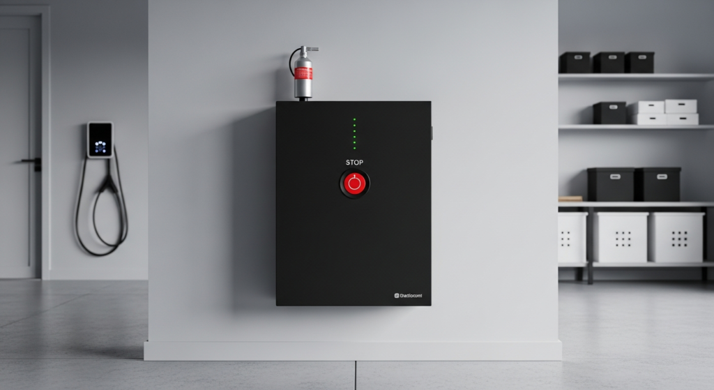
- UL 9540A – Test Method for Evaluating Thermal Runaway Fire Propagation: This is not a pass/fail certification but a large-scale fire test. A battery system is forced into thermal runaway in a specialized facility to see if the fire propagates from cell to cell, module to module, and finally, out of the unit itself. The results of this test determine the required safety distances between ESS units and from walls, dictating where and how many systems can be installed. Systems that perform well in UL 9540A testing, like our SolarKiit Apex line, can be installed with minimal clearance, maximizing energy density in a given space.
Adherence to these codes is not a burden; it is a design constraint that fosters innovation. It forces engineers to build inherently safer, more robust systems. If you have specific questions about how these regulations apply to your project, please do not hesitate to Contact our engineering team.
The Pillar FAQ: Answering Your Toughest Engineering Questions
1. How does operating temperature critically affect the round-trip efficiency and lifespan of a LiFePO4 battery?
Operating temperature is a primary determinant of both the immediate RTE and long-term degradation of a LiFePO4 battery. While often seen as a secondary factor, temperature dictates the kinetics of the electrochemical reactions within the cell. There is a delicate trade-off that a well-engineered BMS must constantly navigate.
- Higher Temperatures (>35°C): At elevated temperatures, the internal resistance of the battery decreases. This reduces I²R losses during charging and discharging, leading to a marginal, short-term increase in RTE. However, this comes at a steep cost. High temperatures dramatically accelerate parasitic side reactions and the growth of the Solid Electrolyte Interphase (SEI) layer on the anode. This accelerated degradation is irreversible and is the primary cause of capacity fade, permanently reducing the battery’s State of Health (SoH).
- Lower Temperatures (<5°C): At cold temperatures, ion mobility within the electrolyte slows significantly, and internal resistance skyrockets. This causes a sharp drop in RTE, as more energy is wasted as heat just to move the lithium ions. More dangerously, charging a LiFePO4 battery below 0°C at a high rate can cause lithium plating—metallic lithium depositing on the anode surface instead of intercalating. This is not only irreversible and causes permanent capacity loss but can also form dendrites that may pierce the separator, creating an internal short circuit and a major safety hazard.
A premium BMS will use this data to implement active thermal management, using fans or liquid cooling to keep the cells in their optimal window (typically 15°C to 30°C) to balance immediate RTE with long-term health.
2. Why is a high-voltage (e.g., 400V) battery architecture inherently more efficient than a low-voltage (e.g., 48V) system for whole-home backup?
High-voltage architectures significantly reduce resistive losses (I²R losses) throughout the system. This is a fundamental principle of electrical engineering derived from the power formula, P = V × I (Power = Voltage × Current). For a given amount of power transfer, a higher voltage necessitates a lower current. Since energy lost as heat in a conductor is proportional to the square of the current (Ploss = I²R), the benefits are exponential.
- Reduced Conductor Losses: To deliver 8,000 watts of power, a 48V system must push a massive 167 amps (8000W / 48V). A 400V system delivers the same power with just 20 amps (8000W / 400V). This ~8x reduction in current leads to a ~64x reduction in resistive heat loss in the cables for the same wire gauge.
- Thinner, Cheaper Cabling: Because the current is so much lower, high-voltage systems can use significantly thinner and less expensive copper wiring between the battery and the hybrid inverter, reducing material cost and installation complexity.
- Higher Inverter Efficiency: Power electronics like MOSFETs and IGBTs used in inverters also operate more efficiently at higher voltages and lower currents. This is why the efficiency curves of high-voltage hybrid inverters are typically 1-2 percentage points higher than their 48V counterparts, especially under heavy load.
In essence, high-voltage isn’t just a trend; it’s a more elegant and efficient engineering solution for managing residential-scale power.
3. What is the difference between State of Charge (SoC) and State of Health (SoH), and how does the BMS calculate them to optimize efficiency?
SoC is the battery’s current charge level, while SoH is a measure of its remaining capacity compared to its original state. Confusing the two is a common error; they are distinct metrics that a sophisticated BMS must track independently to ensure both safety and performance.
- State of Charge (SoC): This is the “fuel gauge” of the battery, expressed as a percentage from 0% to 100%. The most common method for calculating SoC is coulomb counting—integrating the current flowing in and out of the battery over time. However, this method is prone to drift. Therefore, the BMS must periodically recalibrate the SoC reading by referencing the battery’s open-circuit voltage against a known voltage-to-SoC curve.
- State of Health (SoH): This is a long-term metric of degradation, also expressed as a percentage. A new battery has 100% SoH. A battery with 80% SoH can only store 80% of its original nameplate capacity. SoH is much harder to calculate. Advanced BMS algorithms estimate it by tracking the change in internal resistance over time and measuring the actual capacity during full charge-discharge cycles.
The BMS uses SoH to optimize efficiency and safety. For example, as SoH degrades, the BMS will adjust the upper and lower voltage limits for charging and discharging to prevent stress on the aging cells. It also uses the SoH value to correct the SoC calculation, ensuring that “100% SoC” accurately reflects the full charge of the *current* degraded capacity, not the original capacity. This prevents overcharging and maximizes the usable energy from an aging battery.
4. How does the inverter’s efficiency curve impact the *actual* round-trip efficiency of an energy storage system, beyond its peak rating?
An inverter’s peak efficiency rating is misleading; the efficiency curve across the entire load profile dictates the true energy loss. The peak efficiency (e.g., 98%) published on a datasheet is a marketing number achieved under ideal laboratory conditions, typically at 50-75% of the inverter’s nominal power rating. Real-world household loads are never this constant.
- Low-Load Inefficiency: During the middle of the night, a home’s load might be just 200-300 watts (refrigerator, modem, phantom loads). For a 10kW inverter, this represents only 2-3% of its capacity. At this low operational point, the inverter’s own internal power consumption (for its control boards, fans, etc.) becomes a significant fraction of the output power, and its efficiency can drop to 90% or even lower.
- High-Load Inefficiency: Conversely, when multiple large appliances start simultaneously (e.g., an A/C unit, well pump, and microwave), the surge can push the inverter to its peak or surge limit. Operating at the extreme upper end of its capacity also causes efficiency to drop off as internal components heat up.
The *actual* energy lost in the DC-to-AC conversion is the integral of these efficiency losses over a 24-hour period. A system designer must therefore select an inverter that is not oversized for the typical daily load. Sometimes, using two smaller inverters in parallel can be more efficient than one large inverter, as one can be shut down during periods of low load to keep the other operating in its most efficient range. This is a key strategy for optimizing real-world RTE.
5. Can rapid shutdown requirements, as mandated by the NEC, negatively impact system RTE?
While essential for safety, rapid shutdown systems can introduce minor, often negligible, standby power losses that technically reduce overall RTE. This is a classic engineering trade-off where absolute safety takes precedence over marginal efficiency gains. Rapid shutdown systems, which de-energize controlled conductors to below 30V within 30 seconds of initiation, rely on module-level power electronics (MLPE) that communicate with a central controller.
- Standby Power Consumption: The electronics within each MLPE device and the central controller require a small amount of power to remain in a “keep-alive” state, ready to receive the shutdown signal. This is a parasitic load on the system. While the power draw per device is minuscule (often less than 1 watt), a system with 20-30 panels will have a constant standby load of 20-30 watts, 24/7.
- Cumulative Effect: A 25-watt standby load consumes 0.6 kWh per day (25W × 24h). Over a year, this amounts to 219 kWh. While this is a small fraction of the total energy produced by a typical residential system (e.g., 10,000-15,000 kWh/year), it is a measurable loss that technically reduces the net energy available and thus, the overall system efficiency.
However, it is critical to frame this correctly. This loss is not a design flaw but the non-negotiable energy cost of ensuring firefighter and installer safety. It is a mandated feature, and any attempt to circumvent it for a fractional gain in efficiency would be a gross violation of electrical codes and professional ethics. The focus should be on selecting certified, low-power-consumption rapid shutdown components to minimize this unavoidable loss in high-voltage energy storage.
📥 Associated Resource:

El Kouriani Abde Civil Engineer & Founder of SolarKiit
El Kouriani Abde is a seasoned Civil Engineer and Project Manager with over 21 years of field experience. As the founder and publisher of SolarKiit.com, he leverages his deep technical background to simplify complex renewable energy concepts. His mission is to provide homeowners and professionals with accurate, engineering-grade guides to maximize their solar investments and achieve energy independence.